NIST IR 8320B 日本語訳
英語タイトル : Hardware-Enabled Security: Policy-Based Governance in Trusted Container Platforms日本語タイトル : ハードウェア支援セキュリティ:信頼されたコンテナープラットフォームにおけるポリシーベースのガバナンス
公開日 : 2022-04-20
原文URL : https://csrc.nist.gov/pubs/ir/8320/b/final
翻訳編集 : 自動生成(有志による非公式の日本語訳), 原文取得日 : 2026-10-31, 訳文 : 374 / 375 ブロック
[要約] NIST IR 8320B は、マルチテナントのクラウド環境でコンテナーのデプロイメントを保護するための、ハードウェア支援セキュリティの技法および技術に基づくアプローチを説明する報告書です。このアプローチのプロトタイプ実装についても説明しており、この実装は一般のセキュリティコミュニティにとってのブループリントまたはテンプレートとなることを意図しています。プロトタイプ実装では、プラットフォームアテステーションと計測済みワーカーノード起動、ワークロードの信頼された配置、アセットタグ付けと信頼された場所、信頼に基づくワークロードの暗号化、信頼に基づくワークロードによる情報へのアクセスという五つのステージが説明されています。附属書では、ハードウェアルートオブトラストの実装、OpenShift によるワークロードオーケストレーションの実装、ワークロード暗号化の実装が示されています。
NISTIR 8320B
NISTIR 8320B
Hardware-Enabled Security: Policy-Based Governance in Trusted Container Platforms
ハードウェア支援セキュリティ: 信頼されたコンテナープラットフォームにおけるポリシーベースのガバナンス
Michael Bartock Murugiah Souppaya Haidong Xia Raghu Yeluri Uttam Shetty Brandon Lum Mariusz Sabath Harmeet Singh Alaa Youssef Gosia Steinder Yu Cao Jayashree Ramanathan
Michael Bartock Murugiah Souppaya Haidong Xia Raghu Yeluri Uttam Shetty Brandon Lum Mariusz Sabath Harmeet Singh Alaa Youssef Gosia Steinder Yu Cao Jayashree Ramanathan
This publication is available free of charge from: https://doi.org/10.6028/NIST.IR.8320B
本刊行物は次の URL から無料で入手できます: https://doi.org/10.6028/NIST.IR.8320B
[NIST のロゴ。公的な標章のため、この非公式サイトには掲載していません。原本 PDF を参照してください。]
NISTIR 8320B
NISTIR 8320B
Hardware-Enabled Security: Policy-Based Governance in Trusted Container Platforms
ハードウェア支援セキュリティ: 信頼されたコンテナープラットフォームにおけるポリシーベースのガバナンス
Michael Bartock Murugiah Souppaya Computer Security Division Information Technology Laboratory
Michael Bartock Murugiah Souppaya Computer Security Division Information Technology Laboratory
Haidong Xia Raghu Yeluri Uttam Shetty Intel Corporation Santa Clara, California
Haidong Xia Raghu Yeluri Uttam Shetty Intel Corporation Santa Clara, California
Brandon Lum Mariusz Sabath Harmeet Singh Alaa Youssef Gosia Steinder IBM Armonk, New York
Brandon Lum Mariusz Sabath Harmeet Singh Alaa Youssef Gosia Steinder IBM Armonk, New York
Yu Cao Jayashree Ramanathan Red Hat Raleigh, North Carolina
Yu Cao Jayashree Ramanathan Red Hat Raleigh, North Carolina
This publication is available free of charge from: https://doi.org/10.6028/NIST.IR.8320B
本刊行物は次の URL から無料で入手できます: https://doi.org/10.6028/NIST.IR.8320B
April 2022
2022 年 4 月
U.S. Department of Commerce Gina M. Raimondo, Secretary
米国商務省 Gina M. Raimondo 長官
National Institute of Standards and Technology
米国国立標準技術研究所
Laurie E. Locascio, NIST Director and Undersecretary of Commerce for Standards and Technology
Laurie E. Locascio、NIST 所長兼商務次官(標準・技術担当)
National Institute of Standards and Technology Interagency or Internal Report 8320B 41 pages (April 2022)
米国国立標準技術研究所 省庁間報告書または内部報告書 8320B 全 41 ページ(2022 年 4 月)
This publication is available free of charge from: https://doi.org/10.6028/NIST.IR.8320B
本刊行物は次の URL から無料で入手できます: https://doi.org/10.6028/NIST.IR.8320B
Certain commercial entities, equipment, or materials may be identified in this document in order to describe an experimental procedure or concept adequately. Such identification is not intended to imply recommendation or endorsement by NIST, nor is it intended to imply that the entities, materials, or equipment are necessarily the best available for the purpose.
実験の手順や概念を適切に説明するため、本文書では特定の商業団体、機器、材料に言及している場合があります。こうした言及は、NIST による推奨や推薦を意味するものではなく、それらの団体、材料、機器がその目的に最適であることを意味するものでもありません。
There may be references in this publication to other publications currently under development by NIST in accordance with its assigned statutory responsibilities. The information in this publication, including concepts and methodologies, may be used by federal agencies even before the completion of such companion publications. Thus, until each publication is completed, current requirements, guidelines, and procedures, where they exist, remain operative. For planning and transition purposes, federal agencies may wish to closely follow the development of these new publications by NIST.
本刊行物では、NIST が法令上の責務に従って現在策定中の他の刊行物に言及している場合があります。本刊行物の情報(概念や方法論を含む)は、そうした関連刊行物の完成前であっても、連邦機関が使用してかまいません。したがって、各刊行物が完成するまでは、現行の要件、ガイドライン、手順が存在する場合、それらが引き続き有効です。計画および移行のため、連邦機関は、NIST によるこれらの新しい刊行物の策定状況を注意深く追うことを検討してもよいです。
Organizations are encouraged to review all draft publications during public comment periods and provide feedback to NIST. Many NIST cybersecurity publications, other than the ones noted above, are available at https://csrc.nist.gov/publications.
組織は、公開意見募集の期間中にすべてのドラフト刊行物を確認し、NIST にフィードバックを提供することが推奨されます。上記以外にも、NIST の多くのサイバーセキュリティ刊行物が https://csrc.nist.gov/publications で入手できます。
Submit comments on this publication to: hwsec@nist.gov National Institute of Standards and Technology Attn: Applied Cybersecurity Division, Information Technology Laboratory 100 Bureau Drive (Mail Stop 2000) Gaithersburg, MD 20899-2000
本刊行物へのコメントの送付先: hwsec@nist.gov 米国国立標準技術研究所 宛先: 応用サイバーセキュリティ部門、情報技術研究所 100 Bureau Drive (郵便物受付番号 2000) Gaithersburg, MD 20899-2000
All comments are subject to release under the Freedom of Information Act (FOIA).
すべてのコメントは、情報自由法(FOIA)に基づく公開の対象となります。
Reports on Computer Systems Technology
コンピューターシステム技術に関する報告書
The Information Technology Laboratory (ITL) at the National Institute of Standards and Technology (NIST) promotes the U.S. economy and public welfare by providing technical leadership for the Nation’s measurement and standards infrastructure. ITL develops tests, test methods, reference data, proof of concept implementations, and technical analyses to advance the development and productive use of information technology. ITL’s responsibilities include the development of management, administrative, technical, and physical standards and guidelines for the cost-effective security and privacy of other than national security-related information in federal information systems.
米国国立標準技術研究所(NIST)の情報技術研究所(ITL)は、国の測定・標準のインフラストラクチャーに対する技術的リーダーシップを提供することで、米国の経済と公共の福祉を促進しています。ITL は、情報技術の開発と生産的な利用を推進するため、テスト、テスト方法、参照データ、概念実証の実装、技術分析を開発しています。ITL の責務には、連邦情報システムにおける国家安全保障に関係しない情報について、費用対効果の高いセキュリティとプライバシーのための、管理面、運用面、技術面、物理面の標準およびガイドラインの策定が含まれます。
Abstract
概要
In today’s cloud data centers and edge computing, attack surfaces have significantly increased, cyber attacks are industrialized, and most security control implementations are not coherent or consistent. The foundation of any data center or edge computing security strategy should be securing the platform on which data and workloads will be executed and accessed. The physical platform represents the foundation for any layered security approach and provides the initial protections to help ensure that higher-layer security controls can be trusted. This report explains an approach based on hardware-enabled security techniques and technologies for safeguarding container deployments in multi-tenant cloud environments. It also describes a prototype implementation of the approach intended to be a blueprint or template for the general security community.
今日のクラウドデータセンターやエッジコンピューティングでは、攻撃対象領域が大幅に拡大し、サイバー攻撃は産業化され、ほとんどのセキュリティ対策の実装は一貫性や整合性を欠いています。データセンターやエッジコンピューティングのセキュリティ戦略の基盤となるべきは、データやワークロードが実行・アクセスされるプラットフォームを保護することです。物理プラットフォームは、あらゆる多層的セキュリティアプローチの基盤であり、上位層のセキュリティ対策が信頼できることを保証するための初期保護策を提供します。本報告書は、マルチテナントのクラウド環境でコンテナーのデプロイメントを保護するための、ハードウェアによるセキュリティ技法および技術に基づくアプローチを説明します。また、このアプローチのプロトタイプ実装についても説明します。このプロトタイプ実装は、一般のセキュリティコミュニティにとってのブループリントまたはテンプレートとなることを意図しています。
Keywords
キーワード
cloud; container; hardware-enabled security; hardware root of trust; platform security; trusted compute pool; virtualization.
クラウド; コンテナー; ハードウェアによるセキュリティ; ハードウェアの信頼の基点; プラットフォームセキュリティ; 信頼されたコンピュートプール; 仮想化。
Audience
想定読者
The primary audiences for this report are security professionals, such as security engineers and architects; system administrators and other information technology (IT) professionals for cloud service providers; and hardware, firmware, and software developers who may be able to leverage hardware-enabled security techniques and technologies to improve container deployment in multi-tenant cloud environments.
本報告書の主な想定読者は、セキュリティエンジニアやアーキテクトなどのセキュリティ専門家、クラウドサービスプロバイダーのシステム管理者およびその他の情報技術(IT)専門家、そしてハードウェアによるセキュリティ技法および技術を活用して、マルチテナントのクラウド環境におけるコンテナーのデプロイメントを改善できる可能性のあるハードウェア、ファームウェア、ソフトウェアの開発者です。
Trademark Information
商標情報
All registered trademarks or other trademarks belong to their respective organizations.
登録商標その他の商標は、すべて各組織に帰属します。
Patent Disclosure Notice
特許開示に関する通知
NOTICE: ITL has requested that holders of patent claims whose use may be required for compliance with the guidance or requirements of this publication disclose such patent claims to ITL. However, holders of patents are not obligated to respond to ITL calls for patents and ITL has not undertaken a patent search in order to identify which, if any, patents may apply to this publication.
通知: ITL は、本刊行物のガイダンスまたは要件への準拠に使用が必要となる可能性のある特許請求の範囲を保有する者に対し、それらの特許請求の範囲を ITL に開示するよう要請しました。ただし、特許保有者には ITL の特許開示要請に応じる義務はなく、ITL は、本刊行物に該当する特許があるかどうかを特定するための特許調査を実施していません。
As of the date of publication and following call(s) for the identification of patent claims whose use may be required for compliance with the guidance or requirements of this publication, no such patent claims have been identified to ITL.
発行日の時点で、本刊行物のガイダンスまたは要件への準拠に使用が必要となる可能性のある特許請求の範囲の特定を求める告知を経ましたが、そのような特許請求の範囲は ITL に特定されていません。
No representation is made or implied by ITL that licenses are not required to avoid patent infringement in the use of this publication.
本刊行物の使用にあたり、特許侵害を避けるためにライセンスが不要であるという表明を、ITL は明示的にも黙示的にも行っていません。
Table of Contents
目次
List of Tables
表の一覧
List of Figures
図の一覧
1 Introduction
1 はじめに
1.1 Purpose and Scope
1.1 目的と適用範囲
The purpose of this publication is to describe an approach for safeguarding application container deployments in multi-tenant cloud environments. This publication builds upon selected security challenges involving Infrastructure as a Service (IaaS) that are discussed in NIST Interagency or Internal Report (IR) 8320A [1], which addresses cloud computing technologies and geolocation in the form of resource asset tags. Specifically, it uses the three stages of deployment described in Sections 3, 4, and 5 of NIST IR 8320A, and additionally describes two additional stages for encrypting container images and creating data access policies for containers. It then describes a prototype implementation that was designed to address those challenges. The publication provides sufficient details about the prototype implementation so that organizations can reproduce it if desired. The publication is intended to be a blueprint or template that can be used by the general security community to validate and implement the described implementation.
本刊行物の目的は、マルチテナントのクラウド環境でアプリケーションコンテナーのデプロイメントを保護するためのアプローチを説明することです。本刊行物は、NIST Interagency or Internal Report (IR) 8320A [1] で論じられている Infrastructure as a Service(IaaS)に関する特定のセキュリティ上の課題を土台としています。8320A は、クラウドコンピューティング技術と、リソースのアセットタグという形での地理的位置情報を扱っています。具体的には、NIST IR 8320A の第 3 節、第 4 節、第 5 節で説明されているデプロイメントの 3 つのステージを用い、さらにコンテナーイメージの暗号化とコンテナーのデータアクセスポリシーの作成についての 2 つのステージを追加で説明します。続いて、これらの課題に対処するために設計されたプロトタイプ実装を説明します。本刊行物は、組織が望めば再現できるよう、プロトタイプ実装について十分な詳細を提供します。本刊行物は、一般のセキュリティコミュニティが、ここで説明する実装を検証し実装するために使用できる、ブループリントまたはテンプレートとなることを意図しています。
It is important to note that the prototype implementation presented in this publication is only one possible way to solve the security challenges. It is not intended to preclude the use of other products, services, techniques, etc. that can also solve the problem adequately, nor is it intended to preclude the use of any cloud products or services not specifically mentioned in this publication.
本刊行物で示すプロトタイプ実装は、セキュリティ上の課題を解決する方法の一つにすぎないことに留意することが重要です。同じ問題を適切に解決できる他の製品、サービス、技法などの使用を妨げる意図はなく、本刊行物で特に言及していないクラウド製品やサービスの使用を妨げる意図もありません。
This publication builds upon the terminology and concepts described in NIST IR 8320, Hardware-Enabled Security: Enabling a Layered Approach to Platform Security for Cloud and Edge Computing Use Cases [2]. Reading that NIST IR is a prerequisite for reading this publication because it explains the concepts and defines key terminology used in this publication.
本刊行物は、NIST IR 8320『Hardware-Enabled Security: Enabling a Layered Approach to Platform Security for Cloud and Edge Computing Use Cases』[2] で説明されている用語と概念を土台としています。同 NIST IR は、本刊行物で使用する概念を説明し、主要な用語を定義しているため、これを読むことは本刊行物を読むための前提条件です。
1.2 Terminology
1.2 用語
For consistency with related NIST reports, this report uses the following definitions for trust-related terms:
NIST の関連報告書との一貫性のため、本報告書では、信頼に関する用語について次の定義を使用します。
•Trust: “The confidence one element has in another that the second element will behave as expected.” [3]
•Trust(信頼): 「ある要素が、別の要素が期待どおりに動作するであろうと抱く確信。」[3]
•Trusted: An element that another element relies upon to fulfill critical requirements on its behalf.
•Trusted(信頼される): 別の要素が、自らに代わって重要な要件を満たすために依拠する要素。
•Trusted boot: A system boot where aspects of the hardware and firmware are measured and compared against known good values to verify their integrity and thus their trustworthiness.
•Trusted boot(トラステッドブート): ハードウェアおよびファームウェアの各側面を計測し、既知の正しい値と比較して、それらの完全性、ひいては信頼性を検証するシステムブート。
•Trustworthy: Worthy of being trusted to fulfill whatever critical requirements may be needed.1
•Trustworthy(信頼に値する): 必要となりうる重要な要件が何であれ、それを満たすことを信頼するに値すること。1
1.3 Document Structure
1.3 文書の構成
This document is organized into the following sections and appendices:
本文書は、次の節と附属書で構成されています。
•Section 2 defines the objective for the prototype implementation and the intermediate goals to be met in order to achieve the objective.
•第 2 節では、プロトタイプ実装の目標と、その目標を達成するために満たすべき中間的なゴールを定義します。
•Sections 3 through 7 describe the five stages of the prototype implementation:
•第 3 節から第 7 節では、プロトタイプ実装の 5 つのステージを説明します。
•Stage 0: Have assurance that the platform the container deployment is running on can be trusted
•ステージ 0: コンテナーのデプロイメントが稼働するプラットフォームが信頼できるという保証を得る
•Stage 1: Orchestrate the placement of workloads to launch only on trusted platforms
•ステージ 1: 信頼できるプラットフォーム上でのみ起動するよう、ワークロードの配置をオーケストレーションする
•Stage 2: Be able to continuously monitor and enforce asset tag restrictions
•ステージ 2: アセットタグの制限を継続的に監視し、強制できるようにする
•Stage 3: Enable end users to encrypt their workload images
•ステージ 3: エンドユーザーがワークロードイメージを暗号化できるようにする
•Stage 4: Be able to grant workloads access to sensitive information via authentication mechanisms
•ステージ 4: 認証メカニズムを通じて、ワークロードに機微な情報へのアクセスを許可できるようにする
•The References section lists the references cited throughout the document.
•参考文献の節には、本文書全体で引用している参考文献を一覧にしています。
•Appendix A provides an overview of the high-level hardware architecture of the prototype implementation, as well as details on how Intel platforms implement hardware modules and enhanced hardware-based security functions.
•付録 A では、プロトタイプ実装の高レベルのハードウェアアーキテクチャーの概要と、Intel プラットフォームがハードウェアモジュールおよびハードウェアベースの強化されたセキュリティ機能をどのように実装するかの詳細を示します。
•Appendix B contains supplementary information provided by IBM and Red Hat describing the components and steps required to set up the OpenShift and Multi-Cloud Manager solutions.
•付録 B には、IBM と Red Hat が提供した補足情報として、OpenShift および Multi-Cloud Manager ソリューションのセットアップに必要なコンポーネントと手順を記載しています。
•Appendix C contains supplementary information describing all the required components and steps required to set up the workload encryption implementation.
•付録 C には、ワークロード暗号化の実装のセットアップに必要なすべてのコンポーネントと手順を説明する補足情報を記載しています。
•Appendix D contains supplementary information describing all the required components and steps required to set up the prototype implementation for using the Trusted Service Identity.
•付録 D には、Trusted Service Identity を使用するプロトタイプ実装のセットアップに必要なすべてのコンポーネントと手順を説明する補足情報を記載しています。
•Appendix E lists the major controls from NIST Special Publication (SP) 800-53 Revision 5 that affect the prototype implementation, as well as the security capabilities the prototype provides, and then maps the prototype’s capabilities to the NIST SP 800-53 controls.
•付録 E では、プロトタイプ実装に影響する NIST Special Publication (SP) 800-53 Revision 5 の主要な管理策と、プロトタイプが提供するセキュリティ機能を一覧にし、そのうえでプロトタイプの機能を NIST SP 800-53 の管理策にマッピングします。
•Appendix F maps the major security features of the prototype to Cybersecurity Framework Subcategories.
•付録 F では、プロトタイプの主要なセキュリティ機能を、サイバーセキュリティフレームワークのサブカテゴリにマッピングします。
•Appendix G contains a list of acronyms for the report.
•付録 G には、本報告書の頭字語の一覧を記載しています。
2 Prototype Implementation
2 プロトタイプの実装
This section defines the prototype implementation. Section 2.1 presents the objective. Section 2.2 provides more details, outlining all of the intermediate goals that must be met in order to achieve the desired prototype implementation. These requirements are grouped into five stages of the use case, each of which is examined more closely in Sections 2.2.1 through 2.2.5, respectively.
本節では、プロトタイプ実装を定義します。第 2.1 節で目標を示します。第 2.2 節ではさらに詳しく、目指すプロトタイプ実装を達成するために満たさなければならない中間的なゴールをすべて概説します。これらの要件はユースケースの 5 つのステージにまとめられており、それぞれを第 2.2.1 節から第 2.2.5 節で詳しく検討します。
2.1 Objective
2.1 目標
There are security and privacy concerns with allowing unrestricted container deployment orchestration. A common desire is to only use cloud servers physically located within the same country as the organization, or physically located in the same country as the origin of the information. Whenever multiple container deployments are present on a single cloud server, there is a need to segregate those deployments from each other so that they do not interfere with each other, gain access to each other’s sensitive data, or otherwise compromise the security or privacy of the containers. NIST IR 8320A, Hardware-Enabled Security: Container Platform Security Prototype [1] provides an overview of challenges organizations may face when using cloud-based container workloads, as well as techniques to improve the security of cloud computing and accelerate the adoption of cloud computing technologies by establishing an automated hardware root-of-trust method for enforcing and monitoring platform integrity and geolocation restrictions for cloud servers.
コンテナーのデプロイメントのオーケストレーションを無制限に許可することには、セキュリティおよびプライバシー上の懸念があります。組織と同じ国、または情報の発生元と同じ国に物理的に所在するクラウドサーバーだけを使用したいという要望はよくあります。1 台のクラウドサーバー上に複数のコンテナーデプロイメントが存在する場合は常に、それらが互いに干渉したり、互いの機微なデータにアクセスしたり、その他の形でコンテナーのセキュリティやプライバシーを侵害したりしないよう、デプロイメント同士を分離する必要があります。NIST IR 8320A『Hardware-Enabled Security: Container Platform Security Prototype』[1] は、クラウドベースのコンテナーワークロードを使用する際に組織が直面しうる課題の概要を示すとともに、クラウドサーバーのプラットフォームの完全性と地理的位置の制限を強制および監視する、自動化されたハードウェアルートオブトラストの手法を確立することで、クラウドコンピューティングのセキュリティを向上させ、クラウドコンピューティング技術の導入を加速させる技法を示しています。
The motivation behind this use case is to build upon the stages of NIST IR 8320A and implement additional techniques that leverage hardware roots of trust in server platforms. The integrity and location data of each host are leveraged in the orchestration and protection of workloads, as well as providing workloads access to specific data. Workload orchestration can ensure that containers are instantiated only on server platforms that meet trustworthiness requirements and are in acceptable locations. Orchestration can also involve initial encryption of container images and releasing the decryption keys only to trusted servers. Additionally, the workloads themselves can be assigned identities based on these trusted attributes of the physical servers they reside on and be granted access to sensitive information based on their identities.
このユースケースの動機は、NIST IR 8320A の各ステージを土台として、サーバープラットフォームのハードウェアルートオブトラストを活用する追加の技法を実装することです。各ホストの完全性データと場所データは、ワークロードのオーケストレーションと保護、およびワークロードに特定のデータへのアクセスを提供するために活用されます。ワークロードのオーケストレーションにより、信頼性の要件を満たし、許容される場所にあるサーバープラットフォーム上でのみコンテナーがインスタンス化されるようにできます。また、コンテナーイメージを最初に暗号化し、復号鍵を信頼できるサーバーにのみ解放することもできます。さらに、ワークロード自体に、それが稼働する物理サーバーの信頼できる属性に基づいて識別情報を割り当て、その識別情報に基づいて機微な情報へのアクセスを許可できます。
2.2 Goals
2.2 ゴール
Using trusted compute pools, described in NIST IR 8320A Sections 3 through 5, is a leading approach to aggregate trusted systems and segregate them from untrusted resources, which results in the separation of higher-value, more sensitive workloads from commodity application and data workloads. The principles of operation are to:
NIST IR 8320A の第 3 節から第 5 節で説明されているトラステッドコンピュートプールの使用は、信頼できるシステムを集約し、信頼できないリソースから分離するための代表的なアプローチであり、その結果、価値が高く機微なワークロードを、一般的なアプリケーションやデータのワークロードから分離できます。その運用上の原則は次のとおりです。
1.Create a part of the cloud to meet the specific and varying security requirements of users.
1.ユーザーの個別かつ多様なセキュリティ要件を満たすクラウドの一部を作成します。
2.Control access to that portion of the cloud so that the correct applications (workloads) get deployed there.
2.そのクラウドの一部へのアクセスを制御し、適切なアプリケーション(ワークロード)がそこにデプロイされるようにします。
3.Enable audits of that portion of the cloud so that users can verify compliance.
3.そのクラウドの一部の監査を可能にし、ユーザーがコンプライアンスを検証できるようにします。
Once the trusted compute pools are created, additional techniques can be used to protect the workloads that run on them, or the information that the workloads can access. These additional principles are to:
トラステッドコンピュートプールを作成したら、その上で実行されるワークロード、またはワークロードがアクセスできる情報を保護するために、追加の技法を使用できます。これらの追加の原則は次のとおりです。
4.Encrypt workload images and ensure only specific servers can decrypt them.
4.ワークロードイメージを暗号化し、特定のサーバーだけが復号できるようにします。
5.Ensure that only specific applications with location-based restriction enforcement can access sensitive data.
5.場所に基づく制限の強制が行われている特定のアプリケーションだけが、機微なデータにアクセスできるようにします。
These trusted compute pools allow IT to gain the benefits of the dynamic cloud environment while still enforcing higher levels of protections for their more critical workloads.
これらのトラステッドコンピュートプールにより、IT 部門は、動的なクラウド環境の利点を享受しながら、より重要なワークロードに対して、より高いレベルの保護を引き続き強制できます。
The ultimate goal is to be able to use “trust” as a logical boundary for deploying cloud workloads on server platforms within a cloud. This goal is dependent on smaller prerequisite goals described as stages, which can be thought of as requirements that the solution must meet.
最終的なゴールは、クラウド内のサーバープラットフォームにクラウドワークロードをデプロイする際の論理的な境界として「信頼」を使用できるようにすることです。このゴールは、ステージとして説明する、より小さな前提となるゴールに依存しています。これらはソリューションが満たさなければならない要件と考えることができます。
2.2.1 Stage 0: Platform attestation and measured worker node launch
2.2.1 ステージ 0: プラットフォームアテステーションと計測付きワーカーノード起動
A fundamental component of a solution is having some assurance that the platform the container deployment is running on can be trusted. If the platform is not trustworthy, then not only is it putting the tenant’s application and data at greater risk of compromise, but also there is no assurance that the claimed asset tag of the cloud server is accurate. Having basic assurance of trustworthiness is the initial stage in the solution.
ソリューションの基本的な構成要素は、コンテナーのデプロイメントが稼働するプラットフォームが信頼できるという何らかの保証を得ることです。プラットフォームが信頼に値しない場合、テナントのアプリケーションとデータが危殆化するリスクがより高くなるだけでなく、クラウドサーバーに主張されているアセットタグが正確であるという保証もなくなります。信頼性の基本的な保証を得ることが、ソリューションの最初のステージです。
NIST IR 8320A Section 2.2.1 describes the specific goals of Stage 0.
NIST IR 8320A の第 2.2.1 節で、ステージ 0 の具体的なゴールを説明しています。
2.2.2 Stage 1: Trusted placement of workloads
2.2.2 ステージ 1: ワークロードの信頼された配置
Once stage 0 has been successfully completed, the next objective is to be able to orchestrate the placement of workloads to launch only on trusted platforms. Workload placement is a key attribute of cloud computing, improving scalability and reliability. The purpose of this stage is to ensure that any server that a workload is launched on will meet the required level of security assurance based on the workload security policy.
ステージ 0 が正常に完了したら、次の目標は、信頼できるプラットフォーム上でのみ起動するようにワークロードの配置をオーケストレーションできるようにすることです。ワークロードの配置はクラウドコンピューティングの重要な属性であり、スケーラビリティと信頼性を向上させます。このステージの目的は、ワークロードが起動するどのサーバーも、ワークロードのセキュリティポリシーに基づいて求められるレベルのセキュリティ保証を満たすようにすることです。
NIST IR 8320A Section 2.2.2 describes the specific goals of Stage 1.
NIST IR 8320A の第 2.2.2 節で、ステージ 1 の具体的なゴールを説明しています。
2.2.3 Stage 2: Asset tagging and trusted location
2.2.3 ステージ 2: アセットタグ付けと信頼された場所
This next stage builds upon stage 1 by adding the ability to continuously monitor and enforce asset tag restrictions.
この次のステージは、ステージ 1 を土台として、アセットタグの制限を継続的に監視し強制する機能を追加します。
NIST IR 8320A Section 2.2.3 describes the specific goals of Stage 2.
NIST IR 8320A の第 2.2.3 節で、ステージ 2 の具体的なゴールを説明しています。
2.2.4 Stage 3: Trust-based workload encryption
2.2.4 ステージ 3: 信頼に基づくワークロードの暗号化
This next stage builds upon stage 2 and adds the ability for end users to encrypt their workload images, which provides at-rest cryptographic isolation to help protect consumer data and intellectual property. In order for a compute node to launch a workload instance from an encrypted image, it will need to retrieve the image decryption key. The purpose of this stage is to ensure that only compute nodes with acceptable platform trustworthiness and specific asset tags will be provided the decryption keys for specific workload images.
この次のステージは、ステージ 2 を土台として、エンドユーザーがワークロードイメージを暗号化できる機能を追加します。これにより、保存時の暗号による分離が提供され、利用者のデータと知的財産の保護に役立ちます。コンピュートノードが暗号化されたイメージからワークロードインスタンスを起動するには、イメージの復号鍵を取得する必要があります。このステージの目的は、プラットフォームの信頼性が許容できる水準にあり、かつ特定のアセットタグを持つコンピュートノードにのみ、特定のワークロードイメージの復号鍵が提供されるようにすることです。
Stage 3 includes the following prerequisite goals:
ステージ 3 には、次の前提となるゴールが含まれます。
1.Have trusted asset tag information for each trusted platform instance. Essentially, stage 2 has been completed, and the platform trust measurements and asset tag information can be leveraged during workload deployment.
1.信頼できる各プラットフォームインスタンスについて、信頼できるアセットタグ情報を持つこと。基本的にステージ 2 が完了しており、プラットフォームの信頼性の計測値とアセットタグ情報をワークロードのデプロイメント時に活用できる状態です。
2.Encrypt workload images and protect decryption keys in a key manager. Decryption keys are kept in a key manager so that authorized nodes in the trusted compute pool can retrieve and launch appropriate instances of workload images.
2.ワークロードイメージを暗号化し、復号鍵を鍵マネージャーで保護すること。復号鍵は鍵マネージャーに保管され、トラステッドコンピュートプール内の認可されたノードが、ワークロードイメージの適切なインスタンスを取得して起動できるようにします。
3.Release decryption keys for workload images only to servers with trusted platforms and in trusted locations. Decryption keys are only released to servers that have the appropriate platform trustworthiness and are in allowed locations based on their asset tags.
3.ワークロードイメージの復号鍵を、信頼できるプラットフォームを持ち、かつ信頼できる場所にあるサーバーにのみ解放すること。復号鍵は、適切なプラットフォームの信頼性を備え、アセットタグに基づいて許可された場所にあるサーバーにのみ解放されます。
2.2.5 Stage 4: Trust-based workload access to information
2.2.5 ステージ 4: 信頼に基づくワークロードによる情報へのアクセス
The last stage builds upon stage 3 and adds the ability to grant workloads access to sensitive information. The majority of workloads running in the cloud need some access to data sources or other services, authenticating themselves using a password, application programming interface (API) key, or certificate. Today, this is typically done through secrets that are designed to be stored securely. The purpose of this stage is to ensure that only specific workloads running within a trusted compute pool can use these authentication mechanisms to access sensitive information.
最後のステージは、ステージ 3 を土台として、ワークロードに機微な情報へのアクセスを許可する機能を追加します。クラウドで稼働するワークロードの大半は、データソースやその他のサービスに何らかのアクセスを必要とし、パスワード、アプリケーションプログラミングインターフェース(API)キー、または証明書を使用して自らを認証します。現在これは通常、安全に保管されるよう設計されたシークレットによって行われています。このステージの目的は、トラステッドコンピュートプール内で稼働する特定のワークロードだけが、これらの認証メカニズムを使用して機微な情報にアクセスできるようにすることです。
Stage 4 includes the following prerequisite goals:
ステージ 4 には、次の前提となるゴールが含まれます。
1.Deploy workloads only to cloud servers with trusted platforms and in trusted locations. Essentially, stage 2 has been completed and workloads are running on an appropriate host in the trusted compute pool.
1.ワークロードを、信頼できるプラットフォームを持ち、かつ信頼できる場所にあるクラウドサーバーにのみデプロイすること。基本的にステージ 2 が完了しており、ワークロードがトラステッドコンピュートプール内の適切なホスト上で稼働している状態です。
2.Create an identity for the workload that is signed by its compute node’s root of trust. Each instance of the workload that is instantiated on a compute node will have a unique identity created for it, which is signed by the root of trust on the compute node to prove where it is running.
2.コンピュートノードのルートオブトラストによって署名された、ワークロードの識別情報を作成すること。コンピュートノード上でインスタンス化されるワークロードの各インスタンスには、固有の識別情報が作成され、それがどこで稼働しているかを証明するため、コンピュートノードのルートオブトラストによって署名されます。
3.Grant workloads appropriate access to sensitivity information based on their identity. When accessing sensitive information, the workload will present its identity from goal 2 and will be granted the appropriate level of access to sensitive information. The level of access is predefined and is determined by the function of the workload, the platform trustworthiness, and the location of the compute node it is running on.
3.ワークロードの識別情報に基づいて、機微な情報への適切なアクセスをワークロードに許可すること。機微な情報にアクセスする際、ワークロードはゴール 2 の識別情報を提示し、機微な情報への適切なレベルのアクセスが許可されます。アクセスのレベルはあらかじめ定義されており、ワークロードの機能、プラットフォームの信頼性、およびワークロードが稼働しているコンピュートノードの場所によって決まります。
2.3 Additional Resources
2.3 追加のリソース
For more information on the technical topics being addressed by these stages, see the following NIST publications:
これらのステージで扱う技術的トピックの詳細については、次の NIST 刊行物を参照してください。
•NIST SP 800-128, Guide for Security-Focused Configuration Management of Information Systems https://doi.org/10.6028/NIST.SP.800-128
•NIST SP 800-128, Guide for Security-Focused Configuration Management of Information Systems https://doi.org/10.6028/NIST.SP.800-128
•NIST SP 800-137, Information Security Continuous Monitoring (ISCM) for Federal Information Systems and Organizations https://doi.org/10.6028/NIST.SP.800-137
•NIST SP 800-137, Information Security Continuous Monitoring (ISCM) for Federal Information Systems and Organizations https://doi.org/10.6028/NIST.SP.800-137
•NIST SP 800-144, Guidelines on Security and Privacy in Public Cloud Computing https://doi.org/10.6028/NIST.SP.800-144
•NIST SP 800-144, Guidelines on Security and Privacy in Public Cloud Computing https://doi.org/10.6028/NIST.SP.800-144
•NIST SP 800-147B, BIOS Protection Guidelines for Servers https://doi.org/10.6028/NIST.SP.800-147B
•NIST SP 800-147B, BIOS Protection Guidelines for Servers https://doi.org/10.6028/NIST.SP.800-147B
•Draft NIST SP 800-155, BIOS Integrity Measurement Guidelines https://csrc.nist.gov/publications/detail/sp/800-155/draft
•Draft NIST SP 800-155, BIOS Integrity Measurement Guidelines https://csrc.nist.gov/publications/detail/sp/800-155/draft
•NIST IR 8320, Hardware-Enabled Security: Enabling a Layered Approach to Platform Security for Cloud and Edge Computing Use Cases https://doi.org/10.6028/NIST.IR.8320
•NIST IR 8320, Hardware-Enabled Security: Enabling a Layered Approach to Platform Security for Cloud and Edge Computing Use Cases https://doi.org/10.6028/NIST.IR.8320
•NIST IR 8320A, Hardware-Enabled Security: Container Platform Security Prototype https://doi.org/10.6028/NIST.IR.8320A
•NIST IR 8320A, Hardware-Enabled Security: Container Platform Security Prototype https://doi.org/10.6028/NIST.IR.8320A
3 Prototyping Stage 0
3 ステージ 0 のプロトタイプ作成
This section provides an overview of stage 0 of the prototype implementation (platform attestation and measured worker node launch).
本節では、プロトタイプ実装のステージ 0(プラットフォームアテステーションと計測付きワーカーノード起動)の概要を説明します。
This stage of the use case enables the creation of what are called trusted compute pools. Also known as trusted pools, they are physical or logical groupings of computing hardware in a data center that are tagged with specific and varying security policies, and the access and execution of apps and workloads are monitored, controlled, audited, etc. In this phase of the solution, an attested launch of the platform including the container runtime is deemed as a trusted node and is added to the trusted pool.
このユースケースのこのステージでは、トラステッドコンピュートプールと呼ばれるものを作成できます。トラステッドプールとも呼ばれるこれらは、データセンター内のコンピューティングハードウェアを物理的または論理的にグループ化したもので、個別かつ多様なセキュリティポリシーがタグ付けされ、アプリやワークロードのアクセスと実行が監視、制御、監査などされます。ソリューションのこの段階では、コンテナーランタイムを含むプラットフォームのアテステーション済み起動によって、そのプラットフォームを信頼できるノードとみなし、トラステッドプールに追加します。
Figure 1 depicts the concept of trusted pools. The resources tagged green indicate trusted ones. Critical policies can be defined such that security-sensitive cloud services can only be launched on these trusted resources. For more detailed information and the solution architecture, please refer to Section 3 of NIST IR 8320A.
図 1 は、トラステッドプールの概念を示しています。緑色のタグが付いたリソースは、信頼できるものを示します。セキュリティ上機微なクラウドサービスをこれらの信頼できるリソース上でのみ起動できるように、重要なポリシーを定義できます。詳細な情報とソリューションのアーキテクチャーについては、NIST IR 8320A の第 3 節を参照してください。
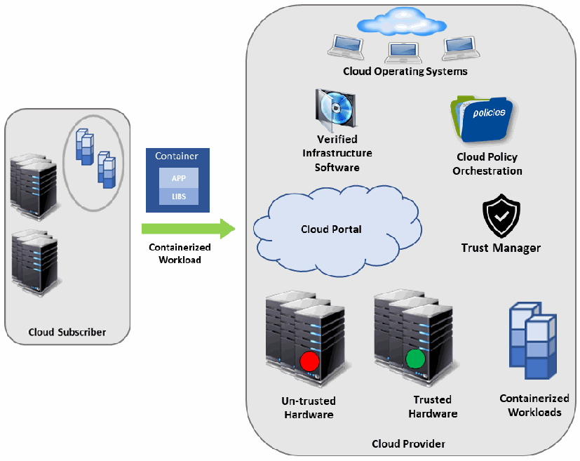
信頼済みプールの概念を示す図です。左側の「Cloud Subscriber」の枠には、サーバーラックと、円で囲んだコンテナ群があります。「APP」と「LIBS」の層を持つ「Container」と、「Containerized Workload」と書かれた緑の矢印が、右側の大きな「Cloud Provider」の枠を指しています。Cloud Provider の枠には、「Cloud Operating Systems」と書かれた雲の下のノートパソコン、「Verified Infrastructure Software」のディスクのアイコン、「policies」と書かれたフォルダー(「Cloud Policy Orchestration」)、「Cloud Portal」の雲、「Trust Manager」の盾のアイコン、赤い点の付いた「Un-trusted Hardware」のサーバーラック、緑の点の付いた「Trusted Hardware」のサーバーラック、積み重ねたブロックの「Containerized Workloads」があります。
Figure 1: Concept of Trusted Pools
図 1: トラステッドプールの概念
4 Prototyping Stage 1
4 ステージ 1 のプロトタイプ作成
This section provides an overview of stage 1 of the prototype implementation (trusted placement of workloads), which is based on the stage 0 work and adds components that orchestrate the placement of workloads to launch on trusted platforms.
本節では、プロトタイプ実装のステージ 1(ワークロードの信頼された配置)の概要を説明します。これはステージ 0 の作業を土台とし、信頼できるプラットフォーム上で起動するようにワークロードの配置をオーケストレーションするコンポーネントを追加します。
Figure 2 shows the components of the stage 1 solution. It assumes that Server A and Server B are two servers within the same cloud.
図 2 は、ステージ 1 のソリューションのコンポーネントを示しています。サーバー A とサーバー B は、同じクラウド内の 2 台のサーバーであると想定しています。
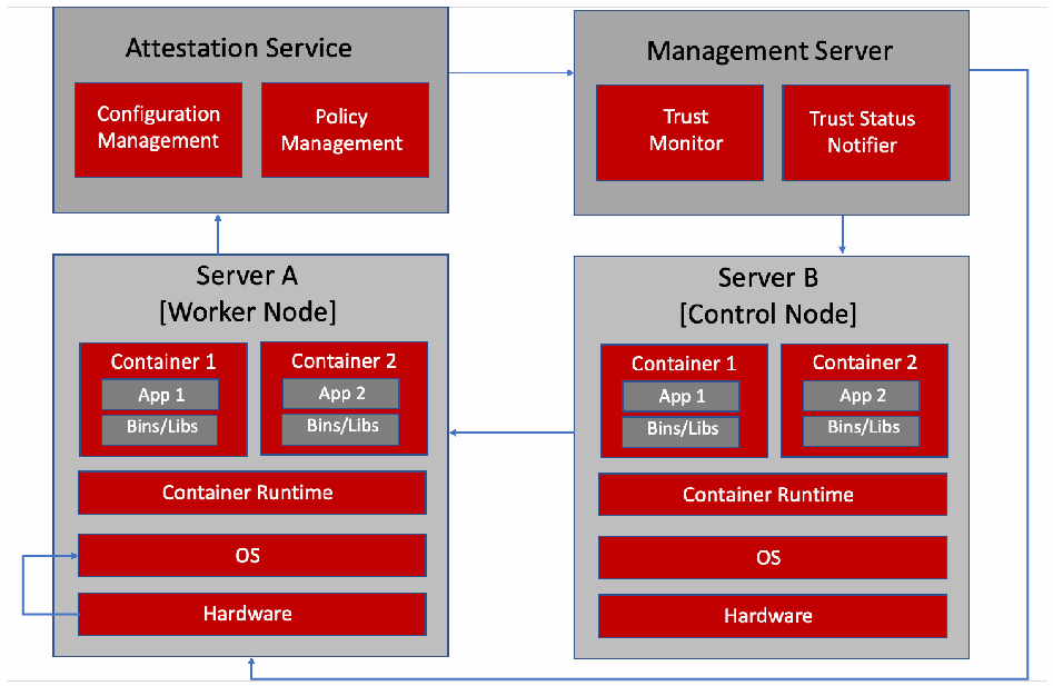
ステージ 1 のソリューションの構成図です。「Attestation Service」は「Configuration Management」と「Policy Management」を含みます。「Management Server」は「Trust Monitor」と「Trust Status Notifier」を含みます。「Server A [Worker Node]」と「Server B [Control Node]」は、それぞれ「Container 1」(「App 1」「Bins/Libs」)、「Container 2」(「App 2」「Bins/Libs」)、「Container Runtime」、「OS」、「Hardware」を含みます。矢印は、Server A から Attestation Service へ、Attestation Service から Management Server へ、Management Server から Server B へ、Server B から Server A のコンテナへ、Management Server から回り込んで Server A の Hardware へ、Server A の中で Hardware から OS へ向かっています。
Figure 2: Stage 1 Solution Overview
図 2: ステージ 1 のソリューション概要
The solution is comprised of four main components: a control node, a worker node, an attestation service, and a management server. They all work together to deploy container workloads only to worker nodes in a trusted compute pool. For detailed information about the solution overview and the interaction of its components, please refer to Section 4 of NIST IR 8320A.
このソリューションは、コントロールノード、ワーカーノード、アテステーションサービス、管理サーバーの 4 つの主要なコンポーネントで構成されます。これらが連携して、コンテナーワークロードをトラステッドコンピュートプール内のワーカーノードにのみデプロイします。ソリューションの概要とそのコンポーネント間の相互作用の詳細については、NIST IR 8320A の第 4 節を参照してください。
5 Prototyping Stage 2
5 ステージ 2 のプロトタイプ作成
This section discusses stage 2 of the prototype implementation (trust-based and asset tag-based secure workload placement), which is based on the stage 1 work and adds components that take into account asset tag restrictions. The solution architecture is the same as stage 1; however, the additional asset tag measurement is leveraged in the server hardware roots of trust and is taken into account during deployment of workloads.
本節では、プロトタイプ実装のステージ 2(信頼とアセットタグに基づく安全なワークロード配置)を説明します。これはステージ 1 の作業を土台とし、アセットタグの制限を考慮するコンポーネントを追加します。ソリューションのアーキテクチャーはステージ 1 と同じですが、サーバーハードウェアのルートオブトラストで追加のアセットタグ計測を活用し、ワークロードのデプロイメント時にそれを考慮します。
Additionally, the capability of monitoring measurements in a governance, risk, and compliance dashboard is introduced in stage 2. For detailed information about the solution overview and a high-level example of what the dashboard may look like, please refer to Section 4 of NIST IR 8320A.
さらにステージ 2 では、ガバナンス・リスク・コンプライアンスのダッシュボードで計測値を監視する機能を導入します。ソリューションの概要とダッシュボードの概略例の詳細については、NIST IR 8320A の第 4 節を参照してください。
6 Prototyping Stage 3
6 ステージ 3 のプロトタイプ作成
This section discusses stage 3 of the prototype implementation (trust-based workload decryption), which is based on the stage 2 work and adds components that allow encrypted container images to be decrypted by servers with trusted platform measurements and asset tags.
本節では、プロトタイプ実装のステージ 3(信頼に基づくワークロードの復号)を説明します。これはステージ 2 の作業を土台とし、信頼できるプラットフォーム計測値とアセットタグを持つサーバーが、暗号化されたコンテナーイメージを復号できるようにするコンポーネントを追加します。
6.1 Solution Overview
6.1 ソリューションの概要
Consumers who place their workloads in the cloud or the edge are typically forced to accept that their workloads are secured by their service providers without insight or knowledge as to what security mechanisms are in place. The ability for end users to encrypt their workload images can provide at-rest cryptographic isolation to help protect consumer data and intellectual property.
ワークロードをクラウドやエッジに置く利用者は通常、どのようなセキュリティメカニズムが導入されているかの洞察も知識もないまま、自らのワークロードがサービスプロバイダーによって保護されていることを受け入れざるをえません。エンドユーザーがワークロードイメージを暗号化できれば、保存時の暗号による分離が提供され、利用者のデータと知的財産の保護に役立ちます。
When the runtime node service receives the launch request, it can detect that the image is encrypted and make a request to retrieve the decryption key. This request can be passed through an attestation service so that an internal trust evaluation for the platform can be performed. The key request is forwarded to the key broker with proof that the platform has been attested. The key broker can then verify the attested platform report and release the key back to the cloud service provider and node runtime services. At that time the node runtime can decrypt the image and proceed with the normal workload orchestration. The disk encryption kernel subsystem can provide at-rest encryption for the workload on the platform.
ランタイムノードサービスは、起動要求を受け取ると、イメージが暗号化されていることを検出し、復号鍵を取得する要求を出すことができます。この要求はアテステーションサービスを経由させ、プラットフォームの内部的な信頼性評価を実施できます。鍵要求は、プラットフォームがアテステーション済みであることの証拠とともに、鍵ブローカーに転送されます。その後、鍵ブローカーはアテステーション済みのプラットフォームレポートを検証し、クラウドサービスプロバイダーとノードのランタイムサービスに鍵を返して解放できます。その時点で、ノードのランタイムはイメージを復号し、通常のワークロードオーケストレーションに進むことができます。ディスク暗号化のカーネルサブシステムは、プラットフォーム上のワークロードに保存時の暗号化を提供できます。
6.2 Solution Architecture
6.2 ソリューションのアーキテクチャー
Figure 3 shows the operation of the stage 3 solution. It assumes that Server A and Server B are two servers within the same cloud. It uses the same base architecture as stages 1 and 2, but it introduces two additional components: container registry and key broker. The container registry is where encrypted container images are stored, and the key broker stores their decryption keys and can provide trusted servers with access to the keys.
図 3 は、ステージ 3 のソリューションの動作を示しています。サーバー A とサーバー B は、同じクラウド内の 2 台のサーバーであると想定しています。ステージ 1 および 2 と同じ基本アーキテクチャーを使用しますが、コンテナーレジストリと鍵ブローカーという 2 つのコンポーネントを追加します。コンテナーレジストリは暗号化されたコンテナーイメージが保管される場所であり、鍵ブローカーはそれらの復号鍵を保管し、信頼できるサーバーに鍵へのアクセスを提供できます。
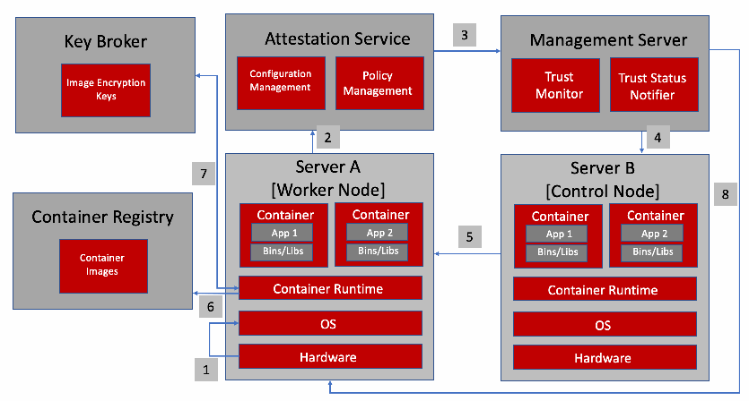
ステージ 3 のソリューションのアーキテクチャ図です。ステージ 1 の図に「Key Broker」(「Image Encryption Keys」を含む)と「Container Registry」(「Container Images」を含む)を加えています。番号付きの手順は、1: Server A の Hardware から OS へ、2: Server A から「Attestation Service」(「Configuration Management」「Policy Management」)へ、3: Attestation Service から「Management Server」(「Trust Monitor」「Trust Status Notifier」)へ、4: Management Server から「Server B [Control Node]」へ、5: Server B から「Server A [Worker Node]」へ、6: Container Registry から Server A の Container Runtime へ、7: Key Broker から Server A の Container Runtime へ、8: Management Server から Server A の Hardware へ、です。各サーバーは 2 つのコンテナ(「App 1」/「App 2」、「Bins/Libs」)、「Container Runtime」、「OS」、「Hardware」を含みます。
Figure 3: Stage 3 Solution Architecture
図 3: ステージ 3 のソリューションアーキテクチャー
There are eight generic steps performed in the operation of the stage 3 prototype, as outlined below and reflected by the numbers in Figure 3:
ステージ 3 のプロトタイプの動作では、以下に示し、図 3 の番号にも反映されているとおり、8 つの一般的な手順を実行します。
1.Server A performs a measured launch, with the enhanced hardware-based security features populating the measurements in the hardware module.
1.サーバー A は計測済み起動を実行し、強化されたハードウェアベースのセキュリティ機能が、ハードウェアモジュールに計測値を格納します。
2.Server A sends a quote to the Attestation Service. The quote includes signed hashes of various platform firmware and operating system (OS) components.
2.サーバー A はアテステーションサービスにクォートを送信します。クォートには、プラットフォームのさまざまなファームウェアおよびオペレーティングシステム(OS)コンポーネントの署名付きハッシュが含まれます。
3.The Trust Authority verifies the signature and hash values, and sends the attestation of the platform’s integrity state to the Management Server.
3.トラストオーソリティは署名とハッシュ値を検証し、プラットフォームの完全性の状態のアテステーションを管理サーバーに送信します。
4.The Management Server enforces workload policy requirements on Server B based on user requirements.
4.管理サーバーは、ユーザーの要件に基づいて、サーバー B にワークロードポリシーの要件を強制します。
5.Server B launches workloads that require trusted infrastructure only on server platforms that have been attested to be trusted.
5.サーバー B は、信頼できるインフラストラクチャーを必要とするワークロードを、信頼できるとアテステーションされたサーバープラットフォーム上でのみ起動します。
6.Server A pulls the encrypted workload image from the Container Registry so that it can launch an instance of the workload.
6.サーバー A は、ワークロードのインスタンスを起動できるように、コンテナーレジストリから暗号化されたワークロードイメージを取得します。
7.The Key Broker releases the workload decryption key to Server A only if it has a trusted attestation report, and Server A launches an instance of the workload.
7.鍵ブローカーは、サーバー A が信頼できるアテステーションレポートを持つ場合にのみ、ワークロードの復号鍵をサーバー A に解放し、サーバー A はワークロードのインスタンスを起動します。
8.Each server platform gets audited periodically based on its measurement values.
8.各サーバープラットフォームは、その計測値に基づいて定期的に監査されます。
7 Prototyping Stage 4
7 プロトタイピングのステージ 4
This section discusses stage 4 of the prototype implementation (trust-based workload access to information), which is based on the stage 3 work and adds components that create identities for individual workloads so that they can be granted appropriate access to sensitivity information.
本節では、プロトタイプ実装のステージ 4(信頼に基づくワークロードによる情報へのアクセス)を説明します。これはステージ 3 の作業を土台とし、個々のワークロードの識別情報を作成して、機微な情報への適切なアクセスを許可できるようにするコンポーネントを追加します。
7.1 Solution Overview
7.1 ソリューションの概要
The majority of workloads running in the cloud need some access to data sources or other services. To do this, they must authenticate themselves using a password, API key, or certificate. Today, this is typically done through secrets. Even though secrets are designed to be stored securely (for example, encrypted at rest) by the orchestration, they can simply be mounted to an arbitrary container and read by anyone who has access to the namespace, including cloud administrators. Those knowing the secret can also access the sensitive data that needs to be protected. The problem with the secrets is that once they are stored, they are also available to administrators, cloud operators, or anyone else with access to the namespace, whether or not they are authorized to access the data that the secrets protect.
クラウドで稼働するワークロードの大半は、データソースやその他のサービスに何らかのアクセスを必要とします。そのためには、パスワード、API キー、または証明書を使用して自らを認証しなければなりません。現在、これは通常シークレットによって行われています。シークレットは、オーケストレーションによって安全に保管(たとえば保存時に暗号化)されるよう設計されていますが、任意のコンテナーにマウントするだけで、クラウド管理者を含む、その名前空間にアクセスできる誰でも読み取ることができます。シークレットを知っている人は、保護すべき機微なデータにもアクセスできます。シークレットの問題は、一度保管されると、そのシークレットが保護するデータへのアクセスが認可されているかどうかにかかわらず、管理者、クラウドオペレーター、またはその名前空間にアクセスできるその他の人も、そのシークレットを利用できることです。
Trust-based workload access to information protects sensitive data access by ensuring only attested services with specific location-based restrictions can access the secrets. This is done through the use of workload identity, which is composed of the trusted hardware identity data that has been fully attested, including the data center location and region, and various runtime measurements to identify the application. These measurements are securely signed by a service running on each worker node, using a chain of trust created during the secure bootstrapping of the environment, then continuously attested and validated. The bootstrapping of the environment requires configuring a secret store that runs a root Certificate Authority (CA), and installing an intermediate CA and token signing service on each worker node. Each worker node with the token signing service uses its hardware root of trust to protect its individual private key.
信頼に基づくワークロードによる情報へのアクセスは、場所に基づく特定の制限を満たす、アテステーション済みのサービスのみがシークレットにアクセスできるようにすることで、機微なデータへのアクセスを保護します。これは、ワークロードの識別情報を使用して行われます。ワークロードの識別情報は、データセンターの場所やリージョンを含め、完全にアテステーションされた信頼できるハードウェアの識別データと、アプリケーションを識別するためのさまざまなランタイム計測値で構成されます。これらの計測値は、環境の安全なブートストラップ時に作成された信頼の連鎖を使用して、各ワーカーノードで稼働するサービスによって安全に署名され、その後継続的にアテステーションおよび検証されます。環境のブートストラップには、ルート認証局(CA)を実行するシークレットストアの設定と、各ワーカーノードへの中間 CA およびトークン署名サービスのインストールが必要です。トークン署名サービスを持つ各ワーカーノードは、ハードウェアルートオブトラストを使用して、それぞれの秘密鍵を保護します。
7.2 Solution Architecture
7.2 ソリューションのアーキテクチャー
It is assumed that all the steps from stage 3 have been completed, and that a workload is successfully deployed to a worker node before any steps of this stage begin. Figure 4 shows the operation of the stage 4 solution, with the assumptions that the workload deployed is on top of a trusted worker node and policies have been defined for the measurements of the application that can access secrets. These measurements represent the identity of the application.
このステージの手順を開始する前に、ステージ 3 のすべての手順が完了しており、ワークロードがワーカーノードに正常にデプロイされていると想定しています。図 4 は、ステージ 4 のソリューションの動作を示しています。ここでは、デプロイされたワークロードが信頼できるワーカーノード上にあり、シークレットにアクセスできるアプリケーションの計測値に対するポリシーが定義されていることを前提とします。これらの計測値は、アプリケーションの識別情報を表します。
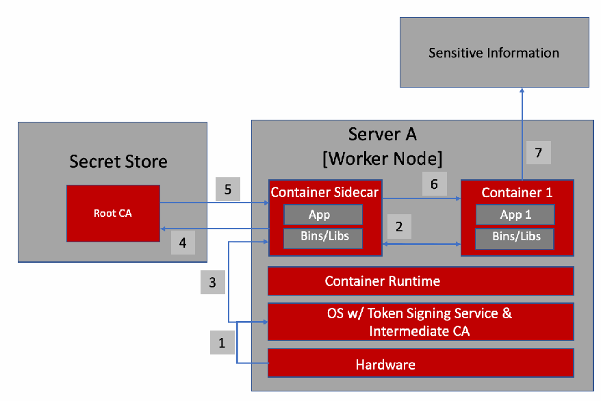
ステージ 4 のソリューションのアーキテクチャ図です。「Secret Store」は「Root CA」を含みます。「Server A [Worker Node]」は「Container Sidecar」(「App」「Bins/Libs」)、「Container 1」(「App 1」「Bins/Libs」)、「Container Runtime」、「OS w/ Token Signing Service & Intermediate CA」、「Hardware」を含みます。Server A の上に「Sensitive Information」があります。番号付きの矢印は、1: Hardware からトークン署名サービスを持つ OS へ、2: Container Sidecar と Container 1 の間、3: Container Sidecar から OS のトークン署名サービスへ、4: Container Sidecar から Secret Store の Root CA へ、5: Root CA から Container Sidecar へ、6: Container Sidecar から Container 1 へ、7: Container 1 から Sensitive Information へ向かっています。
Figure 4: Stage 4 Solution Architecture
図 4: ステージ 4 のソリューションアーキテクチャー
There are seven generic steps performed in the operation of the stage 4 prototype, as outlined below and reflected by the numbers in Figure 4:
ステージ 4 のプロトタイプの動作では、以下に示し、図 4 の番号にも反映されているとおり、7 つの一般的な手順を実行します。
1.Server A has been bootstrapped by installing an intermediate CA that contains a signing authority which uses the hardware root of trust to protect its private key.
1.サーバー A は、ハードウェアルートオブトラストを使用して秘密鍵を保護する署名機関を含む中間 CA をインストールすることで、ブートストラップされています。
2.When Server A instantiates a workload instance with its sidecar, the sidecar collects the measurements called claims that define the identity of this application.
2.サーバー A がサイドカー付きでワークロードインスタンスをインスタンス化すると、サイドカーは、このアプリケーションの識別情報を定義する、クレームと呼ばれる計測値を収集します。
3.The workload sidecar sends the measurements securely to the token signing service on Server A, and the signing service signs these claims using the intermediate CA, then returns the token to the sidecar.
3.ワークロードのサイドカーは、計測値をサーバー A のトークン署名サービスに安全に送信し、署名サービスは中間 CA を使用してこれらのクレームに署名し、トークンをサイドカーに返します。
4.The sidecar requests the annotated secrets from the secret store by passing the signed token along with the request.
4.サイドカーは、署名付きトークンを要求とともに渡すことで、注釈付きのシークレットをシークレットストアに要求します。
5.The secret store validates the signature and the expiration date on the token, and if everything is valid, it uses the provided claims against the policies to retrieve the secret. If the measurements match the policy, the secret is released to the application.
5.シークレットストアは、トークンの署名と有効期限を検証し、すべてが有効であれば、提供されたクレームをポリシーに照らしてシークレットを取得します。計測値がポリシーに一致する場合、シークレットはアプリケーションに解放されます。
6.The sidecar injects the secret into the running workload instance.
6.サイドカーは、シークレットを稼働中のワークロードインスタンスに注入します。
7.The running workload instance can easily access the secret locally and use it to obtain sensitive data.
7.稼働中のワークロードインスタンスは、シークレットにローカルで容易にアクセスでき、それを使用して機微なデータを取得できます。
References
参考文献
[1] Bartock M, Souppaya M, Wheeler J, Knoll T, Shetty U, Savino R, Inbaraj J, Righi S, Scarfone K (2021) Hardware-Enabled Security: Container Platform Security Prototype. (National Institute of Standards and Technology, Gaithersburg, MD), NIST Interagency or Internal Report (IR) 8320A. https://doi.org/10.6028/NIST.IR.8320A
[1] Bartock M, Souppaya M, Wheeler J, Knoll T, Shetty U, Savino R, Inbaraj J, Righi S, Scarfone K (2021) Hardware-Enabled Security: Container Platform Security Prototype. (National Institute of Standards and Technology, Gaithersburg, MD), NIST Interagency or Internal Report (IR) 8320A. https://doi.org/10.6028/NIST.IR.8320A
[2] Bartock M, Souppaya M, Savino R, Knoll T, Shetty U, Cherfaoui M, Yeluri R, Malhotra A, Banks D, Jordan M, Pendarakis D, Rao JR, Romness P, Scarfone KA (2022) Hardware-Enabled Security: Enabling a Layered Approach to Platform Security for Cloud and Edge Computing Use Cases. (National Institute of Standards and Technology, Gaithersburg, MD), NIST Interagency or Internal Report (IR) 8320. https://doi.org/10.6028/NIST.IR.8320
[2] Bartock M, Souppaya M, Savino R, Knoll T, Shetty U, Cherfaoui M, Yeluri R, Malhotra A, Banks D, Jordan M, Pendarakis D, Rao JR, Romness P, Scarfone KA (2022) Hardware-Enabled Security: Enabling a Layered Approach to Platform Security for Cloud and Edge Computing Use Cases. (National Institute of Standards and Technology, Gaithersburg, MD), NIST Interagency or Internal Report (IR) 8320. https://doi.org/10.6028/NIST.IR.8320
[3] Polydys ML, Wisseman S (2009) Software Assurance in Acquisition: Mitigating Risks to the Enterprise. https://apps.dtic.mil/dtic/tr/fulltext/u2/a495389.pdf
[3] Polydys ML, Wisseman S (2009) Software Assurance in Acquisition: Mitigating Risks to the Enterprise. https://apps.dtic.mil/dtic/tr/fulltext/u2/a495389.pdf
[4] Joint Task Force (2020) Security and Privacy Controls for Information Systems and Organizations. (National Institute of Standards and Technology, Gaithersburg, MD), NIST Special Publication (SP) 800-53, Rev. 5. Includes updates as of December 10, 2020. https://doi.org/10.6028/NIST.SP.800-53r5
[4] Joint Task Force (2020) Security and Privacy Controls for Information Systems and Organizations. (National Institute of Standards and Technology, Gaithersburg, MD), NIST Special Publication (SP) 800-53, Rev. 5. 2020 年 12 月 10 日時点の更新を含みます。https://doi.org/10.6028/NIST.SP.800-53r5
[5] National Institute of Standards and Technology (2018), Framework for Improving Critical Infrastructure Cybersecurity, Version 1.1. (National Institute of Standards and Technology, Gaithersburg, MD). https://doi.org/10.6028/NIST.CSWP.04162018
[5] National Institute of Standards and Technology (2018), Framework for Improving Critical Infrastructure Cybersecurity, Version 1.1. (National Institute of Standards and Technology, Gaithersburg, MD). https://doi.org/10.6028/NIST.CSWP.04162018
Appendix A—Hardware Root of Trust Implementation
付録 A—ハードウェアルートオブトラストの実装
This appendix provides an overview of the high-level hardware architecture of the prototype implementation, as well as details on how Intel platforms implement hardware modules and enhanced hardware-based security functions.
本附属書では、プロトタイプ実装の高レベルのハードウェアアーキテクチャーの概要と、Intel プラットフォームがハードウェアモジュールおよびハードウェアベースの強化されたセキュリティ機能をどのように実装するかの詳細を示します。
A.1 High-Level Implementation Architecture
A.1 高レベルの実装アーキテクチャー
Figure 5 shows the high-level implementation architecture. The Intel Security Libraries for Data Center (ISecL-DC) server (in the upper left corner) contains the key broker service, attestation service, and utilities for attesting the hardware root of trust and host measurements. Descriptions of each component and installation steps are in the ISecL-DC product guide.
図 5 は、高レベルの実装アーキテクチャーを示しています。Intel Security Libraries for Data Center(ISecL-DC)サーバー(左上隅)には、鍵ブローカーサービス、アテステーションサービス、およびハードウェアルートオブトラストとホスト計測値をアテステーションするためのユーティリティが含まれています。各コンポーネントの説明とインストール手順は、ISecL-DC 製品ガイドに記載されています。
There are two OpenShift clusters, one comprised of virtual machines (VMs) running on a VMware cluster, and another comprised of VMs running on kernel-based virtual machines (KVMs) plus one bare metal host. The first cluster is used as a management cluster, while the second is a managed cluster.
OpenShift クラスターは 2 つあります。1 つは VMware クラスター上で稼働する仮想マシン(VM)で構成され、もう 1 つは Kernel-based Virtual Machine(KVM)上で稼働する VM と 1 台のベアメタルホストで構成されます。1 つ目のクラスターは管理クラスターとして使用され、2 つ目は被管理クラスターです。
•The managed cluster is the cluster in which the trusted workloads will run. There can be multiple managed clusters governed by the IBM Cloud Pak for Multicloud Management (MCM).
•被管理クラスターは、信頼できるワークロードが稼働するクラスターです。IBM Cloud Pak for Multicloud Management(MCM)によって管理される被管理クラスターを複数持つことができます。
•The management cluster contains the control plane for MCM, as well as DevOps-related tooling.
•管理クラスターには、MCM のコントロールプレーンと、DevOps 関連のツールが含まれます。
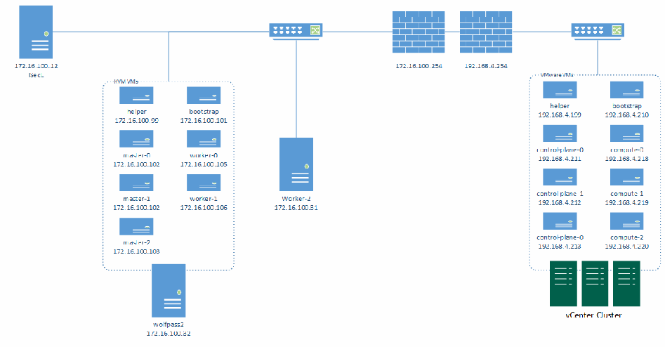
プロトタイプ実装のアーキテクチャを示すネットワーク図です。左上に「ISecL」サーバー(172.16.100.12)があります。スイッチを介して、点線で囲んだ「KVM VMs」のグループ: helper 172.16.100.99、bootstrap 172.16.100.101、master-0 172.16.100.102、worker-0 172.16.100.105、master-1 172.16.100.102、worker-1 172.16.100.106、master-2 172.16.100.103(サーバー「wolfpass2」(172.16.100.32)上でホスト)と、ベアメタルサーバー「Worker-2」(172.16.100.31)につながっています。2 台のファイアウォール(172.16.100.254 と 192.168.4.254)は、2 つ目のスイッチに接続され、そのスイッチは点線で囲んだ「VMware VMs」のグループ: helper 192.168.4.199、bootstrap 192.168.4.210、control-plane-0 192.168.4.211、compute-0 192.168.4.218、control-plane-1 192.168.4.212、compute-1 192.168.4.219、control-plane-0 192.168.4.213、compute-2 192.168.4.220(「vCenter Cluster」上で稼働)につながっています。
Figure 5: Prototype Implementation Architecture
図 5: プロトタイプ実装のアーキテクチャー
A.2 Hardware Root of Trust: Intel TXT and Trusted Platform Module (TPM)
A.2 ハードウェアルートオブトラスト: Intel TXT とトラステッドプラットフォームモジュール(TPM)
Hardware-based root-of-trust, when coupled with an enabled BIOS, OS, and components, constitutes the foundation for a more secure computing platform. This secure platform ensures BIOS and OS integrity at boot from rootkits and other low-level attacks. It establishes the trustworthiness of the server and host platforms.
ハードウェアベースのルートオブトラストは、有効化された BIOS、OS、コンポーネントと組み合わされることで、より安全なコンピューティングプラットフォームの基盤を構成します。この安全なプラットフォームにより、ブート時の BIOS と OS の完全性が、ルートキットやその他の低レベルの攻撃から保証されます。これはサーバーおよびホストプラットフォームの信頼性を確立します。
There are three roots of trust in a trusted platform: root of trust for measurement (RTM), root of trust for reporting (RTR), and root of trust for storage (RTS). They are the foundational elements of a single platform. These are the system elements that must be trusted because misbehavior in these normally would not be detectable in the higher layers. In an Intel Trusted Execution Technology (TXT)-enabled platform, the RTM is the Intel microcode: the Core-RTM (CRTM). An RTM is the first component to send integrity-relevant information (measurements) to the RTS. Trust in this component is the basis for trust in all the other measurements. RTS contains the component identities (measurements) and other sensitive information. A trusted platform module (TPM) provides the RTS and RTR capabilities in a trusted computing platform.
トラステッドプラットフォームには、計測のルートオブトラスト(RTM)、報告のルートオブトラスト(RTR)、保管のルートオブトラスト(RTS)という 3 つのルートオブトラストがあります。これらは単一のプラットフォームの基盤となる要素です。これらは、不正な動作が通常は上位層で検知できないため、信頼しなければならないシステム要素です。Intel Trusted Execution Technology(TXT)が有効なプラットフォームでは、RTM は Intel のマイクロコードである Core-RTM(CRTM)です。RTM は、完全性に関連する情報(計測値)を RTS に最初に送信するコンポーネントです。このコンポーネントへの信頼が、他のすべての計測値への信頼の基礎となります。RTS には、コンポーネントの識別情報(計測値)とその他の機微な情報が含まれます。トラステッドプラットフォームモジュール(TPM)は、トラステッドコンピューティングプラットフォームにおいて RTS および RTR の機能を提供します。
Intel TXT is the RTM, and it is a mechanism to enable visibility, trust, and control in the cloud. Intel TXT is a set of enhanced hardware components designed to protect sensitive information from software-based attacks. Intel TXT features include capabilities in the microprocessor, chipset, I/O subsystems, and other platform components. When coupled with an enabled OS and enabled applications, these capabilities safeguard the confidentiality and integrity of data in the face of increasingly hostile environments.
Intel TXT は RTM であり、クラウドにおける可視性、信頼、制御を可能にするメカニズムです。Intel TXT は、機微な情報をソフトウェアベースの攻撃から保護するよう設計された、強化されたハードウェアコンポーネントの集合です。Intel TXT の機能には、マイクロプロセッサー、チップセット、I/O サブシステム、その他のプラットフォームコンポーネントの能力が含まれます。有効化された OS やアプリケーションと組み合わせることで、これらの能力は、ますます敵対的になる環境においてもデータの機密性と完全性を保護します。
Intel TXT incorporates a number of secure processing innovations, including:
Intel TXT には、次のような多くのセキュア処理の革新が組み込まれています。
•Protected execution: Lets applications run in isolated environments so that no unauthorized software on the platform can observe or tamper with the operational information. Each of these isolated environments executes with the use of dedicated resources managed by the platform.
•保護された実行: アプリケーションを分離された環境で実行させ、プラットフォーム上の許可されていないソフトウェアが運用情報を観察したり改ざんしたりできないようにします。これらの分離された環境はそれぞれ、プラットフォームが管理する専用リソースを使用して実行されます。
•Sealed storage: Provides the ability to encrypt and store keys, data, and other sensitive information within the hardware. This can only be decrypted by the same environment that encrypted it.
•封印されたストレージ: 鍵、データ、その他の機微な情報を、ハードウェア内で暗号化して保管する機能を提供します。これは、それを暗号化したのと同じ環境でのみ復号できます。
•Attestation: Enables a system to provide assurance that the protected environment has been correctly invoked and to take a measurement of the software running in the protected space. This is achieved by the attestation process defined in the next subsection. The information exchanged during this process is known as the attestation identity key credential and is used to establish mutual trust between parties.
•アテステーション: 保護された環境が正しく呼び出されたことの保証をシステムが提供し、保護された領域で稼働しているソフトウェアの計測を行えるようにします。これは、次の小節で定義するアテステーションプロセスによって実現されます。このプロセスで交換される情報はアテステーション識別鍵クレデンシャルと呼ばれ、当事者間の相互の信頼を確立するために使用されます。
•Protected launch: Provides the controlled launch and registration of critical system software components in a protected execution environment.
•保護された起動: 保護された実行環境において、重要なシステムソフトウェアコンポーネントの制御された起動と登録を提供します。
Intel Xeon® Platinum Scalable processor series and the previous generation Xeon Processor E3, Xeon Processor E5, and Xeon Processor E7 series processors support Intel TXT.
Intel Xeon® Platinum Scalable プロセッサーシリーズ、および旧世代の Xeon Processor E3、Xeon Processor E5、Xeon Processor E7 シリーズのプロセッサーは Intel TXT をサポートしています。
Intel TXT works through the creation of a measured launch environment (MLE) enabling an accurate comparison of all the critical elements of the launch environment against a known good source. Intel TXT creates a cryptographically unique identifier for each approved launch-enabled component and then provides a hardware-based enforcement mechanism to block the launch of any code that does not match or, alternately, indicate when an expected trusted launch has not happened through a process of secure remote attestation. In the latter case, when an attestation indicates that one or more measured components in the MLE do not match expectations, orchestration of workloads can be prevented on the suspect platform, even though the platform itself still launches. This hardware-based solution provides the foundation on which IT administrators can build trusted platform solutions to protect against aggressive software-based attacks and to better control their virtualized or cloud environments.
Intel TXT は、計測済み起動環境(MLE)を作成することで機能し、起動環境のすべての重要な要素を既知の正常な情報源と正確に比較できるようにします。Intel TXT は、承認された起動可能な各コンポーネントに暗号学的に一意な識別子を作成し、一致しないコードの起動を阻止するハードウェアベースの強制メカニズムを提供するか、あるいは、安全なリモートアテステーションのプロセスを通じて、期待される信頼できる起動が行われなかったことを示します。後者の場合、アテステーションによって MLE 内の計測済みコンポーネントの 1 つ以上が期待と一致しないことが示されれば、プラットフォーム自体は起動するものの、疑わしいプラットフォーム上でのワークロードのオーケストレーションを阻止できます。このハードウェアベースのソリューションは、IT 管理者が巧妙なソフトウェアベースの攻撃から保護し、仮想化環境やクラウド環境をより適切に制御するためのトラステッドプラットフォームソリューションを構築する基盤となります。
A.3 Attestation: Intel Security Libraries (ISecL)
A.3 アテステーション: Intel Security Libraries(ISecL)
An attestation authority provides the definitive answers to these questions. Attestation provides cryptographic proof of compliance, utilizing the root of trust concept to provide actionable security controls by making the information from various roots of trust visible and usable by other entities. Figure 6 illustrates the attestation protocol providing the means for conveying measurements to the challenger. The endpoint attesting device must have a means of measuring the BIOS firmware, low-level device drivers, and OS and other measured components, and forwarding those measurements to the attestation authority. The attesting device must do this while protecting the integrity, authenticity, nonrepudiation, and in some cases, confidentiality of those measurements.
これらの問いに対する決定的な答えを提供するのが、アテステーション機関です。アテステーションは、コンプライアンスの暗号学的な証明を提供します。ルートオブトラストの概念を利用して、さまざまなルートオブトラストからの情報を他のエンティティが見て利用できるようにすることで、実行可能なセキュリティ管理策を提供します。図 6 は、チャレンジャーに計測値を伝える手段を提供するアテステーションプロトコルを示しています。アテステーションを行うエンドポイントデバイスには、BIOS ファームウェア、低レベルのデバイスドライバー、OS、その他の計測対象コンポーネントを計測し、それらの計測値をアテステーション機関に転送する手段がなければなりません。アテステーションを行うデバイスは、これらの計測値の完全性、真正性、否認防止、場合によっては機密性を保護しながら、これを行わなければなりません。
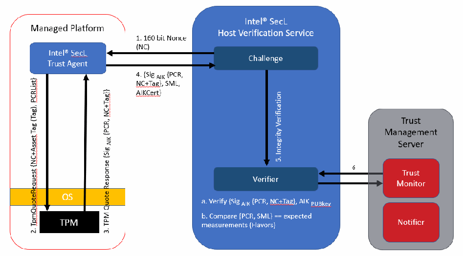
リモートアテステーションのプロトコルを示す図です。左の「Managed Platform」は「Intel® SecL Trust Agent」「OS」「TPM」を含みます。中央の「Intel® SecL Host Verification Service」は「Challenge」と「Verifier」を含みます。右の「Trust Management Server」は「Trust Monitor」と「Notifier」を含みます。矢印は、「1. 160 bit Nonce (NC)」が Challenge から Trust Agent へ、「2. TpmQuoteRequest {NC+Asset Tag (Tag), PCRList}」が Trust Agent から TPM へ、「3. TPM Quote Response {Sig AIK {PCR, NC+Tag}}」が TPM から Trust Agent へ、「4. {Sig AIK {PCR, NC+Tag}, SML, AIKCert}」が Trust Agent から Challenge へ、「5. Integrity Verification」が Challenge から Verifier へ、「6」が Verifier と Trust Monitor の間です。Verifier の下に「a. Verify {Sig AIK {PCR, NC+Tag}, AIK PUBkey」と「b. Compare {PCR, SML} == expected measurements (Flavors)」と書かれています。
Figure 6: Remote Attestation Protocol
図 6: リモートアテステーションプロトコル
Here are the steps shown in Figure 6 for the remote attestation protocol:
リモートアテステーションプロトコルについて、図 6 に示す手順は次のとおりです。
1.The challenger, at the request of a requester, creates a non-predictable nonce (NC) and sends it to the attestation agent on the attesting node, along with the selected list of Platform Configuration Registers (PCRs).
1.チャレンジャーは、要求者からの要求に応じて、予測不可能なナンス(NC)を作成し、選択したプラットフォーム構成レジスター(PCR)のリストとともに、アテステーションを受けるノードのアテステーションエージェントに送信します。
2.The attestation agent sends that request to the TPM as a TPMQuoteRequest with the nonce and the PCR list.
2.アテステーションエージェントは、その要求を、ナンスと PCR のリストを含む TPMQuoteRequest として TPM に送信します。
3.In response to the TPMQuoteRequest, the TPM loads the attestation identity key (AIK) from protected storage in the TPM by using the storage root key (SRK), then performs a TPM Quote command, which is used to sign the selected PCRs and the NC with the private key AIKpriv. Additionally, the attesting agent retrieves the stored measurement log (SML).
3.TPM は、TPMQuoteRequest に応答して、ストレージルート鍵(SRK)を使用して TPM 内の保護されたストレージからアテステーション識別鍵(AIK)を読み込み、次に TPM Quote コマンドを実行します。このコマンドは、選択された PCR と NC に秘密鍵 AIKpriv で署名するために使用されます。加えて、アテステーションエージェントは、保存されている計測ログ(SML)を取得します。
4.In the integrity response step, the attesting agent sends the response consisting of the signed quote, signed NC, and the SML to the challenger. The attesting agent also delivers the AIK credential, which consists of the AIKpub that was signed by a Privacy-CA.
4.完全性応答のステップで、アテステーションエージェントは、署名付きクォート、署名付き NC、SML からなる応答をチャレンジャーに送信します。アテステーションエージェントは、Privacy-CA によって署名された AIKpub からなる AIK クレデンシャルも送り届けます。
5.For the integrity verification step:
5.完全性検証のステップは次のとおりです。
a.The challenger validates if the AIK credential was signed by a trusted Privacy-CA, thus belonging to a genuine TPM. The challenger also verifies whether AIKpub is still valid by checking the certificate revocation list of the trusted issuing party.
a.チャレンジャーは、AIK クレデンシャルが信頼できる Privacy-CA によって署名されており、したがって正規の TPM に属していることを検証します。チャレンジャーは、信頼できる発行者の証明書失効リストを確認することで、AIKpub がまだ有効かどうかも検証します。
b.The challenger verifies the signature of the quote and checks the freshness of the quote.
b.チャレンジャーは、クォートの署名を検証し、クォートの新鮮さを確認します。
c.Based on the received SML and the PCR values, the challenger processes the SML, compares the individual module hashes that are extended to the PCRs against the “good known or golden values,” and recomputes the received PCR values. If the individual values match the golden values and if the computed values match the signed aggregate, the remote node is asserted to be in a trusted state.
c.チャレンジャーは、受信した SML と PCR 値に基づいて SML を処理し、PCR に拡張された個々のモジュールのハッシュを「既知の正しい値、すなわちゴールデン値」と比較し、受信した PCR 値を再計算します。個々の値がゴールデン値に一致し、かつ計算された値が署名された集約値に一致すれば、リモートノードは信頼できる状態にあると表明されます。
6.The verifier informs the manager of the trust state of the remote node. The manager records the trust state in its management database and uses it for any individual or aggregated device status requests. If an administrator is subscribed to trust-related events, the manager will also send email notifications when a managed remote node is detected as being untrusted.
6.検証者は、リモートノードの信頼状態をマネージャーに通知します。マネージャーは、その信頼状態を管理データベースに記録し、個々のデバイスまたは集約されたデバイスの状態要求に使用します。管理者が信頼に関するイベントを購読している場合、マネージャーは、被管理リモートノードが信頼できないと検出されたときに、電子メールによる通知も送信します。
This protocol can help mitigate replay attacks, tampering, and masquerading.
このプロトコルは、リプレイ攻撃、改ざん、なりすましの緩和に役立ちます。
Once the ISecL trust agent and host verification service are installed successfully, asset tags can be created and provisioned to each managed server. Section 6.4 in the ISecL-DC v1.6 product guide describes the steps of creating and provisioning asset tags.
ISecL のトラストエージェントとホスト検証サービスが正常にインストールされると、アセットタグを作成し、管理対象の各サーバーにプロビジョニングできます。アセットタグの作成とプロビジョニングの手順は、ISecL-DC v1.6 製品ガイドの第 6.4 節に記載されています。
Appendix B—Workload Orchestration Implementation: OpenShift
付録 B—ワークロードオーケストレーションの実装: OpenShift
This section contains supplementary information describing all the components and steps required to set up the prototype implementation for OpenShift.
本節には、OpenShift 向けのプロトタイプ実装のセットアップに必要なすべてのコンポーネントと手順を説明する補足情報を記載しています。
B.1 Prototype Architecture
B.1 プロトタイプのアーキテクチャー
Kubernetes has become a popular source for building large web-scale technologies that enable the enterprise to take advantage of innovations like analytics, artificial intelligence, machine learning, and cloud services. Supporting advanced technologies and building cloud-native applications requires enterprise-grade platforms such as Red Hat OpenShift. This section describes the provisioning and configuration of OpenShift clusters. Figure 7 shows how the nodes from Figure 5 (in Appendix A) in the architecture are logically implemented into two OpenShift clusters and the Remote Attestation Server.
Kubernetes は、エンタープライズが分析、人工知能、機械学習、クラウドサービスなどの革新を活用できるようにする、大規模なウェブスケールの技術を構築するための一般的な基盤となっています。高度な技術をサポートし、クラウドネイティブなアプリケーションを構築するには、Red Hat OpenShift のようなエンタープライズグレードのプラットフォームが必要です。本節では、OpenShift クラスターのプロビジョニングと構成について説明します。図 7 は、アーキテクチャーの(付録 A の)図 5 のノードが、2 つの OpenShift クラスターとリモートアテステーションサーバーとして論理的にどのように実装されているかを示しています。
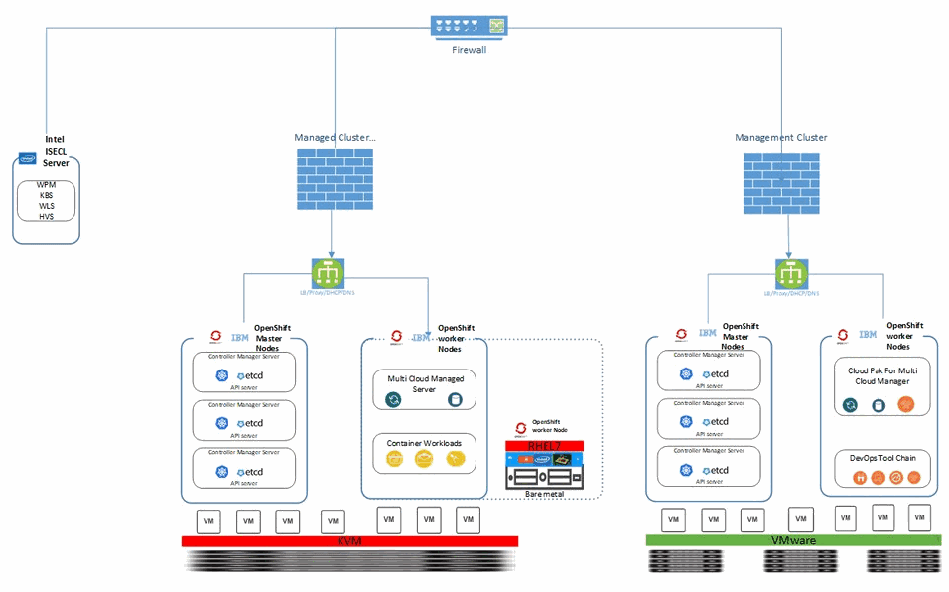
プロトタイプのアーキテクチャ図です。上部の「Firewall」が、「Intel ISECL Server」(「WPM」「KBS」「WLS」「HVS」を含む)、「Managed Cluster」のファイアウォール、「Management Cluster」のファイアウォールにつながっています。各クラスターのファイアウォールはロードバランサー(「LB/Proxy/DHCP/DNS」)につながります。Managed Cluster には「OpenShift Master Nodes」(「etcd」と「API server」を持つ 3 つの「Controller Manager Server」)、「OpenShift worker Nodes」(「Multi Cloud Managed Server」と「Container Workloads」)、「Bare metal」上の「RHEL7」で動く「OpenShift worker Node」があり、VM は「KVM」の層の上で動きます。Management Cluster には「OpenShift Master Nodes」(「etcd」と「API server」を持つ 3 つの「Controller Manager Server」)と「OpenShift worker Nodes」(「Cloud Pak For Multi Cloud Manager」と「DevOps Tool Chain」)があり、VM は「VMware」の層の上で動きます。ノード群の横に製品のロゴ(OpenShift、IBM、Intel、Kubernetes)があります。
Figure 7: Prototype Architecture
図 7: プロトタイプのアーキテクチャー
To implement use cases, OpenShift is deployed in two separate clusters: a Management Cluster based on VMWare, and a Managed Cluster based on KVM infrastructure. Each cluster has three control-plane and three worker nodes, and a VM with load balancer and Domain Name System (DNS) to simulate the trusted container workload environment. MCM components are deployed on both OpenShift clusters. The Managed Cluster has an MCM Hub component, which aggregates information from multiple clusters using an asynchronous work request model. The hub cluster (Management Cluster) maintains the status of clusters and applications, and provides a set of APIs for the various functions to support as a central controller. The Managed Cluster has an MCM managed-cluster component used to define the cluster, with the MCM Klusterlet and other resources configured to initiate a connection to the hub cluster. The Managed Cluster receives work requests and applies them, then returns the results.
ユースケースを実装するため、OpenShift を 2 つの別々のクラスター、すなわち VMware ベースの管理クラスターと、KVM インフラストラクチャーベースの被管理クラスターにデプロイします。各クラスターには、3 つのコントロールプレーンノードと 3 つのワーカーノードがあり、信頼できるコンテナーワークロード環境を模擬するために、ロードバランサーとドメインネームシステム(DNS)を備えた VM があります。MCM コンポーネントは両方の OpenShift クラスターにデプロイされます。管理クラスターには MCM Hub コンポーネントがあり、非同期の作業要求モデルを使用して複数のクラスターからの情報を集約します。ハブクラスター(管理クラスター)は、クラスターとアプリケーションの状態を維持し、中央コントローラーとしてさまざまな機能をサポートする一連の API を提供します。被管理クラスターには、クラスターを定義するために使用される MCM の managed-cluster コンポーネントがあり、MCM Klusterlet とその他のリソースが、ハブクラスターへの接続を開始するよう構成されています。被管理クラスターは作業要求を受け取って適用し、結果を返します。
B.2 OpenShift Installation and Configuration
B.2 OpenShift のインストールと設定
Managing the OpenShift platform in multiple places comes with challenges like complexity, governance, and cost. For example, how do you gain visibility into all the clusters to see where the application’s components are running? How do you know which systems are failing? How can you monitor usage across the clouds and clusters? How do you govern the configuration and changes to this environment? IBM Cloud Pak for Multicloud Management/Red Hat Advanced Cluster Management for Kubernetes supports the use cases. It is based on the Kubernetes community direction and includes advanced functions important to running enterprise-grade environments.
OpenShift プラットフォームを複数の場所で管理することには、複雑さ、ガバナンス、コストといった課題が伴います。たとえば、アプリケーションのコンポーネントがどこで稼働しているかを確認するために、すべてのクラスターの可視性をどのように得るのでしょうか。どのシステムで障害が発生しているかをどのように把握するのでしょうか。複数のクラウドとクラスターにわたる使用状況をどのように監視できるのでしょうか。この環境の構成と変更をどのように統制するのでしょうか。IBM Cloud Pak for Multicloud Management/Red Hat Advanced Cluster Management for Kubernetes は、これらのユースケースをサポートします。これは Kubernetes コミュニティの方向性に基づいており、エンタープライズグレードの環境の運用に重要な高度な機能を含んでいます。
The Policies repository, which is part of the Manager hub component, resides on the Management Cluster. The repository comes with default compliance and policies templates, but our use cases developed new policies that reflected our environment to integrate with the Intel attestation hub. The repository holds the policy defined for the Managed Cluster, and the policy document is applied by using placement bind.
Manager hub コンポーネントの一部であるポリシーリポジトリは、管理クラスターに存在します。このリポジトリには、既定のコンプライアンスおよびポリシーのテンプレートが付属していますが、本ユースケースでは、Intel アテステーションハブと統合するため、当該環境を反映した新しいポリシーを開発しました。リポジトリには被管理クラスター向けに定義されたポリシーが保持されており、ポリシー文書は placement bind を使用して適用されます。
B.2.1 VMware-Based Management Cluster (Cluster A)
B.2.1 VMware ベースの管理クラスター(クラスター A)
Hardware Requirement: For deploying OpenShift Container Platform (OCP) 4.3 on VMware, the minimum recommendation is to provision one ESXi server and one Centos/Red Hat VM on the same virtual local area network (VLAN) in the local datacenter. For this deployment, the setup was an ESXi bare-metal server with 48 CPUs, 256 GB random-access memory (RAM), and 2 TB storage. The Centos/Red Hat VM is only required for a few hours and can be de-provisioned after the install is complete.
ハードウェア要件: VMware に OpenShift Container Platform (OCP) 4.3 をデプロイする場合、最小の推奨構成は、ローカルデータセンター内の同じ仮想ローカルエリアネットワーク(VLAN)上に、ESXi サーバー 1 台と Centos/Red Hat VM 1 台をプロビジョニングすることです。今回のデプロイメントでは、48 CPU、256 GB のランダムアクセスメモリー(RAM)、2 TB のストレージを備えた ESXi ベアメタルサーバーをセットアップしました。Centos/Red Hat VM は数時間だけ必要で、インストール完了後にデプロビジョニングできます。
Networking: The IP addresses used in this process and the configuration files came from our National Cybersecurity Center of Excellence (NCCoE) environment. They are used here for illustration purposes only. Besides setting up your ESXi and vCenter server, you need to have a minimum of 16 IP addresses to assign to the VMs. Each VM node takes one IP address. The recommended minimum of 16 IP addresses is determined by: 1 helper node + 1 boot node + 3 control-plane nodes + 3 worker nodes = 8 nodes. The extra IP addresses are available in case additional worker nodes are required in the future. This installation provisioned the vCenter on the same IP subnet, so a total of 9 IP addresses were used.
ネットワーク: この手順で使用する IP アドレスと設定ファイルは、国立サイバーセキュリティ卓越センター(NCCoE)の環境のものです。ここでは説明のためにのみ使用しています。ESXi と vCenter サーバーのセットアップに加えて、VM に割り当てるための IP アドレスが最低 16 個必要です。各 VM ノードは IP アドレスを 1 つ使用します。推奨される最低 16 個の IP アドレスは、ヘルパーノード 1 + ブートノード 1 + コントロールプレーンノード 3 + ワーカーノード 3 = 8 ノードから決まります。余分な IP アドレスは、将来ワーカーノードを追加する必要が生じた場合のためのものです。このインストールでは vCenter を同じ IP サブネット上にプロビジョニングしたため、合計 9 個の IP アドレスを使用しました。
VMware OCP VM Requirements: Table 1 lists the VMs that are instantiated on the VMware server, along with their virtual hardware requirements and the roles they serve in the cluster.
VMware OCP の VM 要件: 表 1 は、VMware サーバー上でインスタンス化される VM を、その仮想ハードウェア要件およびクラスター内で果たす役割とともに一覧にしたものです。
Table 1: VMs Instantiated on the VMware-Based Management Cluster
表 1: VMware ベースの管理クラスターでインスタンス化される VM
| Node Name | vCPU | Mem (GB) | HDD (GB) | Role |
|---|---|---|---|---|
| Helper Node | 4 | 16 | 150 | LB/DNS/Proxy/DHCP/OCP Installer |
| Bootstrap-0 | 4 | 16 | 150 | Bootstrap OCP |
| Control-plane-0 | 4 | 16 | 150 | Controller OCP |
| Control-plane-1 | 4 | 16 | 150 | Controller OCP |
| Control-plane-2 | 4 | 16 | 150 | Controller OCP |
| compute-0 | 4 | 16 | 150 | Compute OCP |
| compute-1 | 4 | 16 | 150 | Compute OCP |
| compute-2 | 4 | 16 | 150 | Compute OCP |
| ノード名 | vCPU | メモリー(GB) | HDD(GB) | 役割 |
|---|---|---|---|---|
| ヘルパーノード | 4 | 16 | 150 | LB/DNS/プロキシ/DHCP/OCP インストーラー |
| Bootstrap-0 | 4 | 16 | 150 | OCP のブートストラップ |
| Control-plane-0 | 4 | 16 | 150 | OCP コントローラー |
| Control-plane-1 | 4 | 16 | 150 | OCP コントローラー |
| Control-plane-2 | 4 | 16 | 150 | OCP コントローラー |
| compute-0 | 4 | 16 | 150 | OCP コンピュート |
| compute-1 | 4 | 16 | 150 | OCP コンピュート |
| compute-2 | 4 | 16 | 150 | OCP コンピュート |
OCP VMware Deployment Playbooks: To deploy OCP 4.3 on VMware, download the following Git repository: https://github.com/fctoibm/ocpvmware4.3 and follow the steps to run the playbooks. Make sure to change the vars.yaml and host.yaml files to match the networking information for your environment.
OCP VMware デプロイメントのプレイブック: VMware に OCP 4.3 をデプロイするには、次の Git リポジトリをダウンロードし、手順に従ってプレイブックを実行します: https://github.com/fctoibm/ocpvmware4.3 。必ず、vars.yaml と host.yaml のファイルを、使用する環境のネットワーク情報に合わせて変更してください。
B.2.2 KVM-Based Managed Cluster (Cluster B)
B.2.2 KVM ベースの被管理クラスター(クラスター B)
The second OCP cluster is the managed cluster. It contains an MCM Klusterlet, which ensures that each managed cluster adheres to the policy in place.
2 つ目の OCP クラスターは被管理クラスターです。これには MCM Klusterlet が含まれ、各被管理クラスターが、設けられているポリシーに従うようにします。
Hardware Requirement: For this deployment, the lab setup was on a CentOS bare-metal server with 48 CPUs, 256 GB RAM, and 1 TB storage. KVM will be used to create and manage virtual machines. The KVM command line tool is virt-install and the graphical user interface (GUI) tool is virt-manager. To use the KVM GUI tool, install Gnome desktop and VNC on the CentOS bare-metal server. All of the VMs for this managed cluster are deployed on this single KVM host, which has hostname wolfpass2 in the table and image in Figure 5 (in Appendix A).
ハードウェア要件: 今回のデプロイメントでは、ラボのセットアップとして、48 CPU、256 GB の RAM、1 TB のストレージを備えた CentOS ベアメタルサーバーを使用しました。仮想マシンの作成と管理には KVM を使用します。KVM のコマンドラインツールは virt-install、グラフィカルユーザーインターフェース(GUI)ツールは virt-manager です。KVM の GUI ツールを使用するには、CentOS ベアメタルサーバーに Gnome デスクトップと VNC をインストールします。この被管理クラスターのすべての VM は、この 1 台の KVM ホストにデプロイされます。このホストのホスト名は、(付録 A の)図 5 の表とイメージにある wolfpass2 です。
Networking: The IP addresses used in this process and the configuration files came from our NCCoE environment. They are used here for illustration purposes only. When you install OCP in the KVM host environment, you will need a minimum of 16 portable IP addresses. Each VM node takes up one IP address. The recommended minimum of 16 portable IP addresses is determined by: 1 helper node + 1 boot node + 3 control-plane nodes + 3 worker nodes = 8 nodes. The extra IP addresses are available for additional worker nodes required in the future. You should plan your IP address space accordingly.
ネットワーク: この手順で使用する IP アドレスと設定ファイルは、NCCoE の環境のものです。ここでは説明のためにのみ使用しています。KVM ホスト環境に OCP をインストールする場合、ポータブルな IP アドレスが最低 16 個必要です。各 VM ノードは IP アドレスを 1 つ使用します。推奨される最低 16 個のポータブルな IP アドレスは、ヘルパーノード 1 + ブートノード 1 + コントロールプレーンノード 3 + ワーカーノード 3 = 8 ノードから決まります。余分な IP アドレスは、将来必要になる追加のワーカーノードのためのものです。それに応じて IP アドレス空間を計画してください。
KVM OCP VM Requirements: Table 2 lists the VMs that are instantiated on the KVM server, along with their virtual hardware requirements and the roles they serve in the managed cluster.
KVM OCP の VM 要件: 表 2 は、KVM サーバー上でインスタンス化される VM を、その仮想ハードウェア要件および被管理クラスター内で果たす役割とともに一覧にしたものです。
Table 2: VMs Instantiated on the KVM-Based Managed Cluster
表 2: KVM ベースの被管理クラスターでインスタンス化される VM
| Node Name | vCPU | Mem (GB) | HDD (GB) | Role |
|---|---|---|---|---|
| Helper Node | 4 | 16 | 150 | DNS/Proxy/DHCP/OCP Installer |
| Bootstrap | 4 | 16 | 150 | Bootstrap OCP |
| Master0 | 4 | 16 | 150 | Controller OCP |
| Master1 | 4 | 16 | 150 | Controller OCP |
| Master2 | 4 | 16 | 150 | Controller OCP |
| Worker0 | 4 | 16 | 150 | Compute OCP |
| Worker1 | 4 | 16 | 150 | Compute OCP |
| ノード名 | vCPU | メモリー(GB) | HDD(GB) | 役割 |
|---|---|---|---|---|
| ヘルパーノード | 4 | 16 | 150 | DNS/プロキシ/DHCP/OCP インストーラー |
| Bootstrap | 4 | 16 | 150 | OCP のブートストラップ |
| Master0 | 4 | 16 | 150 | OCP コントローラー |
| Master1 | 4 | 16 | 150 | OCP コントローラー |
| Master2 | 4 | 16 | 150 | OCP コントローラー |
| Worker0 | 4 | 16 | 150 | OCP コンピュート |
| Worker1 | 4 | 16 | 150 | OCP コンピュート |
Note: The OpenShift cluster requires three worker nodes; however, since this deployment uses an additional physical server for the third worker node, only two worker node VMs are deployed.
注: OpenShift クラスターにはワーカーノードが 3 つ必要ですが、今回のデプロイメントでは 3 つ目のワーカーノードに追加の物理サーバーを使用するため、ワーカーノードの VM は 2 つだけをデプロイしています。
OCP KVM Deployment Playbooks: To deploy OCP 4.3 on KVM, download the following Git repository: https://github.com/fctoibm/ocpkvm4.3 and follow the steps to run the playbooks. Make sure to change the vars.yaml and host.yaml files to match the networking information of your environment.
OCP KVM デプロイメントのプレイブック: KVM に OCP 4.3 をデプロイするには、次の Git リポジトリをダウンロードし、手順に従ってプレイブックを実行します: https://github.com/fctoibm/ocpkvm4.3 。必ず、vars.yaml と host.yaml のファイルを、使用する環境のネットワーク情報に合わせて変更してください。
The OCP KVM deployment playbook creates all of the worker nodes as virtual machines. In order to create policies bases on hardware roots of trust, a physical server with the Intel TXT and TPM capabilities must be added as an additional worker node to the cluster. This server needs to have the corresponding Red Hat Enterprise Linux (RHEL) OS installed, as well as the Intel Trust Agent as described in Appendix A.2. For the physical server, the OpenShift documentation details how to add an RHEL compute node to an existing cluster.
OCP KVM デプロイメントのプレイブックは、すべてのワーカーノードを仮想マシンとして作成します。ハードウェアルートオブトラストに基づくポリシーを作成するには、Intel TXT と TPM の機能を備えた物理サーバーを、クラスターに追加のワーカーノードとして加える必要があります。このサーバーには、対応する Red Hat Enterprise Linux(RHEL)OS と、付録 A.2 で説明されている Intel Trust Agent をインストールしておく必要があります。物理サーバーについては、既存のクラスターに RHEL コンピュートノードを追加する方法が OpenShift のドキュメントに詳しく記載されています。
B.2.3 Installing MCM Pak 1.3 (MCM HUB - VMware)
B.2.3 MCM Pak 1.3 のインストール(MCM HUB - VMware)
To install MCM Pak 1.3 on OCP 4.3, the setup assumes OCP 4.3 is already installed and administrator-level access is available to deploy the MCM Pak. The guide assumes OCP 4.3 was installed using the same GitHub repository and the same vars.yaml file.
OCP 4.3 に MCM Pak 1.3 をインストールするにあたり、このセットアップでは、OCP 4.3 がすでにインストールされており、MCM Pak をデプロイするための管理者レベルのアクセスが利用できることを前提とします。本ガイドは、OCP 4.3 が同じ GitHub リポジトリと同じ vars.yaml ファイルを使用してインストールされたことを前提としています。
Deploying MCM Pak: The installation Git repository supports two options, VMware or KVM install, and both will deploy a VM guest if required. The VM guest called PakHelper node will act as a client to install MCM Pak. There is no reason to deploy a VM guest client if you already have a VM guest Centos 7 OS available in the same network. If the Centos 7 VM is already in place, please skip options 1 and 2, but if there is no VM guest available, please execute both options 1 or 2 and 3 from the following Git repository: https://github.com/fctoibm/mcmpak1.3 and follow the steps to run the playbooks.
MCM Pak のデプロイ: インストール用 Git リポジトリは VMware と KVM の 2 つのインストールオプションをサポートしており、必要に応じてどちらも VM ゲストをデプロイします。PakHelper ノードと呼ばれる VM ゲストが、MCM Pak をインストールするクライアントとして機能します。同じネットワークに Centos 7 OS の VM ゲストがすでにある場合は、VM ゲストのクライアントをデプロイする理由はありません。Centos 7 の VM がすでにある場合は、オプション 1 と 2 を省略してください。利用可能な VM ゲストがない場合は、次の Git リポジトリにあるプレイブックを実行する手順に従い、オプション 1 または 2 のいずれかとオプション 3 を実行してください: https://github.com/fctoibm/mcmpak1.3
Adding KVM OCP as Managed Cluster in MCM: Once the MCM Pak has been deployed, the KVM OCP cluster can be imported into, and managed by, the IBM MCM. To do so, browse to the web user interface (UI) of MCM and navigate to the Clusters management page. As shown in Figure 8, there is an option to import an existing cluster. To import the existing KVM OCP cluster, perform the steps in this IBM knowledge center article.
MCM での KVM OCP の被管理クラスターとしての追加: MCM Pak のデプロイ後は、KVM OCP クラスターを IBM MCM にインポートして管理できます。そのためには、MCM のウェブユーザーインターフェース(UI)にアクセスし、クラスター管理ページに移動します。図 8 に示すように、既存のクラスターをインポートするオプションがあります。既存の KVM OCP クラスターをインポートするには、この IBM ナレッジセンターの記事の手順を実行します。
IBM Cloud Pak for Multicloud Management の Web コンソールの画面です(アドレスバー: 「Not secure | icp-console.apps.test.ocp.ncco.lab/multicloud/clusters」)。「Clusters」ページの「Add cluster」ダイアログに、「Import an existing cluster by running a command on your cluster.」(選択中)と「You do not have IBM Cloud Automation Manager installed yet. Go to IBM Cloud Automation Manager in the Catalog →」の 2 つの選択肢と、「Cancel」「Select」のボタンがあります。 [第三者の画像。第三者の著作物のため、この非公式サイトには掲載していません。原本 PDF を参照してください。]
Figure 8: MCM Console to Import a Cluster
図 8: クラスターをインポートするための MCM コンソール
Creating Policies for Managed Cluster: Once the KVM OCP cluster has been successfully imported, specific polices that govern workload orchestration can be created and applied. Policies are created in the MCM Hub and these policies are propagated to each managed cluster, where they are enforced. Two policies were put in place for our prototype implementation:
被管理クラスターのポリシーの作成: KVM OCP クラスターが正常にインポートされたら、ワークロードのオーケストレーションを統制する特定のポリシーを作成して適用できます。ポリシーは MCM Hub で作成され、各被管理クラスターに伝播されて、そこで強制されます。このプロトタイプ実装では 2 つのポリシーを設けました。
1.The “Trusted Node Policy” ensures that all nodes in the cluster are trusted and attested. In the inform mode, the policy logs whenever the trust status of a node has been violated. In the enforce mode, the policy drains and removes the node from the cluster.
1.「Trusted Node Policy」は、クラスター内のすべてのノードが信頼でき、アテステーションされていることを保証します。inform モードでは、ノードの信頼状態が侵害されるたびにポリシーがログを記録します。enforce モードでは、ポリシーはそのノードをドレインし、クラスターから削除します。
2.The “Trusted Container Policy” ensures that all workloads run within a namespace are using a set of images from a particular registry path. The infrastructure is set up so only encrypted container images are in that path. This makes it so only encrypted images are run within the namespace.
2.「Trusted Container Policy」は、名前空間内で実行されるすべてのワークロードが、特定のレジストリパスにあるイメージのセットを使用していることを保証します。インフラストラクチャーは、そのパスに暗号化されたコンテナーイメージだけがあるようにセットアップされています。これにより、名前空間内で実行されるのは暗号化されたイメージだけになります。
Figure 9 shows the two policies in the web user interface that have been created for the managed clusters.
図 9 は、被管理クラスター向けに作成された 2 つのポリシーを、ウェブユーザーインターフェースで示したものです。
IBM Cloud Pak for Multicloud Management の Web コンソールの「Governance and risk」ページの画面です(アドレスバー: 「icp-console.apps.test.ocp.ncco.lab/multicloud/policies/all」)。フィルター「NIST CSF」を適用した状態で、「Container policies (2)」、「No violations」と表示された「NIST CSF」の要約パネル、ポリシーの表(列: Policy name、Namespace、Remediation、Cluster violations、Standards、Controls、Categories)があります。表の 2 行は「policy-trustedcontainer」と「policy-trustednode」で、いずれも namespace は「default」、remediation は「inform」、cluster violations は「0/1」、standards は「NIST CSF」、controls は「PR PT 3 Least Functionality」、categories は「PR PT Protective Technology」です。 [第三者の画像。第三者の著作物のため、この非公式サイトには掲載していません。原本 PDF を参照してください。]
Figure 9: Managed Cluster Policies
図 9: 被管理クラスターのポリシー
In addition to these two policies, there is a Tekton task set up as part of the OpenShift pipeline that does a set of checks and encrypts the image. This secure pipeline does building, vulnerability scanning, and encryption. More details on this pipeline are provided in Appendix C.
これら 2 つのポリシーに加えて、OpenShift パイプラインの一部として、一連のチェックを行いイメージを暗号化する Tekton タスクが設定されています。この安全なパイプラインは、ビルド、脆弱性スキャン、暗号化を行います。このパイプラインの詳細は付録 C に記載しています。
Appendix C— Workload Encryption Implementation
付録 C—ワークロード暗号化の実装
This section contains supplementary information describing all the components and steps required to set up the prototype implementation for container workload encryption.
本節には、コンテナーワークロードの暗号化に関するプロトタイプ実装のセットアップに必要なすべてのコンポーネントと手順を説明する補足情報を記載しています。
C.1 Prototype Architecture
C.1 プロトタイプのアーキテクチャー
Refer to Figure 7 from Appendix B for the relevant architecture diagram.
関連するアーキテクチャー図については、付録 B の図 7 を参照してください。
C.2 Workload Encryption Configuration
C.2 ワークロード暗号化の設定
Various parts of the container ecosystem allow the enablement of workload encryption via container image encryption. The technology is based on the Open Container Initiative (OCI) container image specification. The components that support the use of this are:
コンテナーエコシステムのさまざまな部分で、コンテナーイメージの暗号化によるワークロード暗号化を有効にできます。この技術は Open Container Initiative (OCI) のコンテナーイメージ仕様に基づいています。その使用をサポートするコンポーネントは次のとおりです。
•Build: The Skopeo tool is used to encrypt the container images and push them to the registry.
•ビルド: コンテナーイメージの暗号化とレジストリへのプッシュには Skopeo ツールを使用します。
•Runtime: The Cri-o container runtime came as part of OpenShift and was configured to decrypt the images. It is the default runtime of OpenShift 4.3 worker nodes and supports decrypting OCI container images.
•ランタイム: Cri-o コンテナーランタイムは OpenShift に付属しており、イメージを復号するよう設定されました。これは OpenShift 4.3 ワーカーノードの既定のランタイムであり、OCI コンテナーイメージの復号をサポートします。
•Registry: The Docker Distribution registry is used to push, pull, and store the encrypted images. The version used was v2.7.1.
•レジストリ: 暗号化されたイメージのプッシュ、プル、保管には Docker Distribution レジストリを使用します。使用したバージョンは v2.7.1 です。
These are the core components of workload encryption. Several integrations were required with the ISecL Attestation Hub’s APIs to showcase the workload and image encryption with hardware attestation. A custom container encryption metadata scheme was defined to work with the ISecL key broker. The reference implementation code and the document are located at https://github.com/lumjjb/seclkeywrap.
これらがワークロード暗号化の中核コンポーネントです。ハードウェアアテステーションによるワークロードとイメージの暗号化を示すために、ISecL Attestation Hub の API との複数の統合が必要でした。ISecL 鍵ブローカーと連携するため、独自のコンテナー暗号化メタデータスキームが定義されました。リファレンス実装のコードとドキュメントは https://github.com/lumjjb/seclkeywrap にあります。
Key integration points are:
主な統合ポイントは次のとおりです。
•A custom container encryption metadata scheme was defined to work with the ISecL key broker.
•ISecL 鍵ブローカーと連携するため、独自のコンテナー暗号化メタデータスキームが定義されました。
•The core components CRI-0 and Skopeo were patched to enable the use of the custom ISecL protocol. The patches are available at https://github.com/lumjjb/cri-o/tree/sample_integration and https://github.com/lumjjb/skopeo/tree/sample_integration, respectively.
•独自の ISecL プロトコルを使用できるようにするため、中核コンポーネントである CRI-O と Skopeo にパッチが適用されました。パッチはそれぞれ https://github.com/lumjjb/cri-o/tree/sample_integration と https://github.com/lumjjb/skopeo/tree/sample_integration で入手できます。
As part of the DevSecOps cycle, it was integrated with the development flow with the Tekton pipeline to perform builds, security checks, and image encryption. The pipeline workflow can be reached through the OpenShift dashboard by toggling into the Developer role and selecting the “Pipelines” menu, as shown in Figure 10. The definitions of the Tekton objects are available here: https://gist.github.com/lumjjb/22191008f849f240851aec8a1ee0304d
DevSecOps サイクルの一環として、ビルド、セキュリティチェック、イメージ暗号化を行う Tekton パイプラインにより、開発フローと統合されました。パイプラインのワークフローには、図 10 に示すように、OpenShift ダッシュボードで Developer ロールに切り替え、「Pipelines」メニューを選択することでアクセスできます。Tekton オブジェクトの定義は次の場所にあります: https://gist.github.com/lumjjb/22191008f849f240851aec8a1ee0304d
Red Hat OpenShift Container Platform の Web コンソールの「Developer」ビューの画面です(メニュー: +Add、Topology、Builds、Pipelines、Advanced)。プロジェクト「secure-devops」の Pipeline Runs > Pipeline Run Details に「dsop-image-scan-zdv7xz」が表示され、状態は「Succeeded」です。「Pipeline Run Overview」には、完了した 3 つのタスク「build-image」「image-scan…」「image-encr…」が順に並んでいます。その下に Name「dsop-image-scan-zdv7xz」、Namespace「secure-devops」、Labels「tekton.dev/pipeline=dsop-image-scan」があります。 [第三者の画像。第三者の著作物のため、この非公式サイトには掲載していません。原本 PDF を参照してください。]
Figure 10: Creating Pipeline for Image Decryption
図 10: イメージ復号のためのパイプラインの作成
Appendix D—Trusted Service Identity (TSI)
付録 D—Trusted Service Identity(TSI)
This section contains supplementary information describing all the required components and steps required to set up the prototype implementation for the Trusted Service Identity (TSI).
本節には、Trusted Service Identity(TSI)に関するプロトタイプ実装のセットアップに必要なすべてのコンポーネントと手順を説明する補足情報を記載しています。
D.1 TSI Overview
D.1 TSI の概要
TSI protects sensitive data access by ensuring only attested services with specific location-based restrictions can obtain credentials. This is done through the use of workload identity, composed of the trusted hardware identity data that has been fully attested by Intel TXT, including the data center location and region, and various runtime measurements like the image and cluster name, unique pod IDs, and namespace to identify the application. These measurements are securely signed by a service running on every hosting node, using a chain of trust created during the secure bootstrapping of the environment, then continuously attested and validated.
TSI は、場所に基づく特定の制限を満たす、アテステーション済みのサービスのみが認証情報を取得できるようにすることで、機微なデータへのアクセスを保護します。これは、ワークロードの識別情報を使用して行われます。ワークロードの識別情報は、データセンターの場所やリージョンを含め、Intel TXT によって完全にアテステーションされた信頼できるハードウェアの識別データと、アプリケーションを識別するための、イメージ名やクラスター名、一意の Pod ID、名前空間などのさまざまなランタイム計測値で構成されます。これらの計測値は、環境の安全なブートストラップ時に作成された信頼の連鎖を使用して、すべてのホスティングノードで稼働するサービスによって安全に署名され、その後継続的にアテステーションおよび検証されます。
Every container that requires a secret for accessing sensitive data is assigned a short-lived measured identity, in the form of a JSON Web Token (JWT) token, that is signed with the root of trust by the attested process. This measured identity is a form of an ephemeral digital biometric with a short time to live.
機微なデータにアクセスするためのシークレットを必要とするすべてのコンテナーには、アテステーションされたプロセスがルートオブトラストで署名した、JSON Web Token(JWT)トークン形式の、有効期間の短い計測済み識別情報が割り当てられます。この計測済み識別情報は、存続時間の短い一時的なデジタル生体情報の一形態です。
In this implementation, there is a Kubernetes cluster running on OpenShift, extended with TSI, where each node has an intermediate CA signed by the root CA during the secure bootstrapping of the cluster.
この実装では、OpenShift 上で稼働し TSI で拡張された Kubernetes クラスターがあり、各ノードは、クラスターの安全なブートストラップ時にルート CA によって署名された中間 CA を持ちます。
During this bootstrapping, the installation process obtains an attestation report (Security Assertion Markup Language [SAML]) from the Attestation Server for every worker node. This report is checked to verify if all the components are trusted (OS, platform, and software), and the bootstrapping process retrieves worker identity fields from the asset tag of this report. Each worker node also has a JWT Signing Service (JSS) that contains a signing authority that uses the hardware TPM to protect its individual private key.
このブートストラップの間に、インストールプロセスは、すべてのワーカーノードについてアテステーションサーバーからアテステーションレポート(Security Assertion Markup Language [SAML])を取得します。このレポートは、すべてのコンポーネント(OS、プラットフォーム、ソフトウェア)が信頼できるかを検証するために確認され、ブートストラッププロセスは、このレポートのアセットタグからワーカーの識別情報フィールドを取得します。各ワーカーノードには JWT 署名サービス(JSS)もあり、これはハードウェア TPM を使用してそれぞれの秘密鍵を保護する署名機関を含んでいます。
The root CA is securely stored in a vault, which is extended with the TSI Authentication Vault plugin.
ルート CA は、TSI Authentication Vault プラグインで拡張されたボールトに安全に保管されます。
D.2 TSI Installation and Configuration
D.2 TSI のインストールと設定
TSI requires an attestation process to accurately define the identity of the worker nodes hosting the application containers. In this implementation, TSI relies on the ISecL server that has been deployed to provide the identity of the worker nodes. Steps detailing the integration of TSI with ISecL can be found here: https://github.com/IBM/trusted-service-identity/blob/intel-asset/README.md#attestation.
TSI には、アプリケーションコンテナーをホストするワーカーノードの識別情報を正確に定義するためのアテステーションプロセスが必要です。この実装では、TSI は、ワーカーノードの識別情報を提供するためにデプロイされた ISecL サーバーに依拠します。TSI と ISecL の統合手順の詳細は次の場所にあります: https://github.com/IBM/trusted-service-identity/blob/intel-asset/README.md#attestation 。
This process requires two independent phases:
このプロセスには、独立した 2 つのフェーズが必要です。
•Asset Registration with Intel Verification Server – The trusted bootstrapping process responsible for installing the environment must properly set the identity attributes of every worker node. These identity values in the form of asset tags are securely stored in their corresponding TPMs on hosts. As a result, they are included in the SAML attestation report that also includes all the attestation results (OS, platform, software trusted). This process was performed in the steps outlined in Appendix A.
•Intel 検証サーバーへのアセット登録 – 環境のインストールを担うトラステッドなブートストラッププロセスは、すべてのワーカーノードの識別属性を適切に設定しなければなりません。アセットタグの形式をとるこれらの識別値は、ホスト上の対応する TPM に安全に保管されます。その結果、これらは、すべてのアテステーション結果(OS、プラットフォーム、ソフトウェアが信頼できる)も含む SAML アテステーションレポートに含まれます。このプロセスは、付録 A に示した手順で実施しました。
•TSI Deployment with Attestation – The implementation outlined in this document allows for the use of the Intel Attestation Server to obtain the identity of the worker nodes. There are several changes required to configure the TSI installation to support Intel Attestation Server. Additionally, a hardware TPM device is shared between the Intel Trust Agent and the TSI JWT Signing Service, and it requires the use of TPM proxy. For details outlining the suggested configuration changes, visit https://github.com/IBM/trusted-service-identity/blob/intel-asset/README.md#attestation.
•アテステーションを伴う TSI のデプロイメント – 本文書に示す実装では、Intel アテステーションサーバーを使用してワーカーノードの識別情報を取得できます。TSI のインストールが Intel アテステーションサーバーをサポートするよう構成するには、いくつかの変更が必要です。さらに、ハードウェア TPM デバイスは Intel Trust Agent と TSI の JWT 署名サービスの間で共有されるため、TPM プロキシの使用が必要です。推奨される構成変更の詳細は、https://github.com/IBM/trusted-service-identity/blob/intel-asset/README.md#attestation を参照してください。
As a result of these changes, TSI will be installed in the cluster, using an attestation report from the Intel Attestation Service to provide the identities of the workers and to keep the attestation going.
これらの変更の結果、TSI はクラスターにインストールされ、Intel アテステーションサービスからのアテステーションレポートを使用してワーカーの識別情報を提供し、アテステーションを継続します。
Before secrets can be injected into the application container, first they need to be created in the Secret Store (Vault). Follow these steps for injecting secrets into the Vault: https://github.com/IBM/trusted-service-identity/blob/master/examples/vault/README.md#secrets.
シークレットをアプリケーションコンテナーに注入する前に、まずシークレットストア(Vault)にシークレットを作成する必要があります。Vault にシークレットを注入するには、次の手順に従ってください: https://github.com/IBM/trusted-service-identity/blob/master/examples/vault/README.md#secrets 。
Once the application is started, secrets will be injected based on the application identity, including the workload environment and location. As a result, the secret will be delivered to the container runtime memory without ever being stored anywhere in Kubernetes—but from the point of view of the application, no additional changes were needed.
アプリケーションが起動すると、ワークロード環境と場所を含むアプリケーションの識別情報に基づいて、シークレットが注入されます。その結果、シークレットは Kubernetes のどこにも保存されることなくコンテナーランタイムのメモリーに配信されますが、アプリケーションの観点では、追加の変更は必要ありませんでした。
Figure 11 shows a sample JWT created by TSI. Notice its three parts: the header, the payload containing the actual claims, and a signature for validation.
図 11 は、TSI が作成したサンプルの JWT を示しています。ヘッダー、実際のクレームを含むペイロード、検証用の署名という 3 つの部分があることに注目してください。
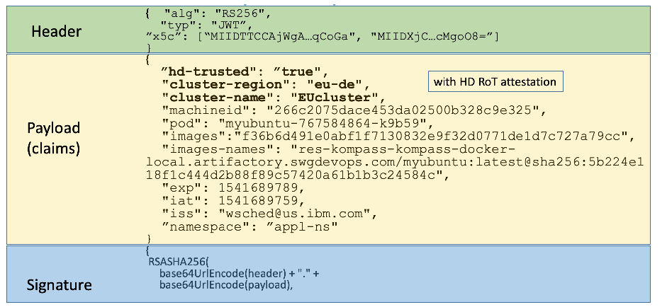
JSON Web Token の例を 3 色の帯で示した図です。「Header」: { "alg": "RS256", "typ": "JWT", "x5c": ["MIIDTTCCAjWgA…qCoGa", "MIIDXjC…cMgoO8="] }。「Payload (claims)」: { "hd-trusted": "true", "cluster-region": "eu-de", "cluster-name": "EUcluster", "machineid": "266c2075dace453da02500b328c9e325", "pod": "myubuntu-767584864-k9b59", "images": "f36b6d491e0abf1f7130832e9f32d0771de1d7c727a79cc", "images-names": "res-kompass-kompass-docker-local.artifactory.swgdevops.com/myubuntu:latest@sha256:5b224e118f1c444d2b88f89c57420a61b1b3c24584c", "exp": 1541689789, "iat": 1541689759, "iss": "wsched@us.ibm.com", "namespace": "appl-ns" }; 最初の 3 つのクレームは太字で、「with HD RoT attestation」と注記されています。「Signature」: { RSASHA256( base64UrlEncode(header) + "." + base64UrlEncode(payload),
Figure 11: Sample JWT Created by TSI
図 11: TSI が作成するサンプルの JWT
The claims included here represent the measured identity of the application. They contain some static values like cluster-region (e.g., Germany, eu-de), cluster-name, individual machineid which is a unique worker node ID, and several runtime measurements like a namespace, unique pod ID, and the list of images making up the pod. These images include the image signature, so you can validate the image and guarantee that the application is running the code that you want to be running and it was not tampered with. The hd-trusted value determines whether all the attested elements are trusted.
ここに含まれるクレームは、アプリケーションの計測済み識別情報を表します。クレームには、cluster-region(例: Germany, eu-de)、cluster-name、ワーカーノードの一意の ID である個別の machineid などの静的な値と、名前空間、一意の Pod ID、Pod を構成するイメージのリストなどのいくつかのランタイム計測値が含まれます。これらのイメージにはイメージの署名が含まれるため、イメージを検証し、アプリケーションが意図したコードを実行していて改ざんされていないことを保証できます。hd-trusted の値は、アテステーションされたすべての要素が信頼できるかどうかを判定します。
Values for cluster-name, cluster-region, and hd-trusted are essential for defining the identity of the compute resources, and they are read from Intel’s Attestation Server. There is also a token expiration timestamp, typically set to one minute, to make these tokens ephemeral and short-lived, protecting the security from leaking. These are the runtime measurements that represent the identity of the application, signed with the root of trust, and used for evaluation against policies controlling the secrets.
cluster-name、cluster-region、hd-trusted の値は、コンピュートリソースの識別情報を定義するうえで不可欠であり、Intel のアテステーションサーバーから読み取られます。トークンの有効期限のタイムスタンプもあり、通常は 1 分に設定されます。これにより、これらのトークンは一時的で短命なものとなり、漏えいからセキュリティを守ります。これらは、アプリケーションの識別情報を表すランタイム計測値であり、ルートオブトラストで署名され、シークレットを制御するポリシーに照らした評価に使用されます。
The secrets stored in the Vault are protected by policies. Policies are composed of the policy-type and the attributes, the same that are used for building claims, and they represent the path to the secret. If the claims provided in the request match the policy attribute path, the secret will be released to the application.
Vault に保管されたシークレットは、ポリシーによって保護されます。ポリシーは、policy-type と属性で構成されます。属性はクレームの構築に使用されるものと同じで、シークレットへのパスを表します。要求で提供されたクレームがポリシーの属性パスと一致すれば、シークレットはアプリケーションに解放されます。
Appendix E—Supporting NIST SP 800-53 Security Controls and Publications
付録 E—NIST SP 800-53 のセキュリティ管理策および刊行物
The major controls in the NIST SP 800-53 Revision 5, Security and Privacy Controls for Information Systems and Organizations [4] control catalog that affect the container platform security prototype implementation are:
NIST SP 800-53 Revision 5『Security and Privacy Controls for Information Systems and Organizations』[4] の管理策カタログのうち、コンテナープラットフォームのセキュリティのプロトタイプ実装に影響する主な管理策は次のとおりです。
•AU-2, Event Logging
•AU-2, Event Logging
•CA-2, Control Assessments
•CA-2, Control Assessments
•CA-7, Continuous Monitoring
•CA-7, Continuous Monitoring
•CM-2, Baseline Configuration
•CM-2, Baseline Configuration
•CM-3, Configuration Change Control
•CM-3, Configuration Change Control
•CM-8, System Component Inventory
•CM-8, System Component Inventory
•IR-4, Incident Handling
•IR-4, Incident Handling
•SA-9, External System Services
•SA-9, External System Services
•SC-1, Policy and Procedures [for System and Communications Protection Family]
•SC-1, Policy and Procedures [for System and Communications Protection Family]
•SC-7, Boundary Protection
•SC-7, Boundary Protection
•SC-29, Heterogeneity
•SC-29, Heterogeneity
•SC-32, System Partitioning
•SC-32, System Partitioning
•SC-36, Distributed Processing and Storage
•SC-36, Distributed Processing and Storage
•SI-3, Malicious Code Protection
•SI-3, Malicious Code Protection
•SI-4, System Monitoring
•SI-4, System Monitoring
•SI-6, Security and Privacy Function Verification
•SI-6, Security and Privacy Function Verification
•SI-7, Software, Firmware, and Information Integrity
•SI-7, Software, Firmware, and Information Integrity
Table 3 lists the security capabilities provided by the prototype:
表 3 は、プロトタイプが提供するセキュリティ機能を一覧にしたものです。
Table 3: Security Capabilities Provided by the Prototype
表 3: プロトタイプが提供するセキュリティ機能
| Capability Category | Capability Number | Capability Name |
|---|---|---|
| IC1 – Measurements | IC1.1 | Measured Boot of BIOS |
| IC1.2 | Baseline for BIOS measurement (allowed list) | |
| IC1.3 | Remote Attestation of Boot Measurements | |
| IC1.4 | Security Capability & Config Discovery | |
| IC2 – Tag Verification | IC2.1 | Asset Tag Verification |
| IC3 – Policy Enforcement | IC3.1 | Policy-Based Workload Provisioning |
| IC3.2 | Policy-Based Workload Migration | |
| IC3.3 | Policy-Based Workload Decryption | |
| IC3.4 | Policy-Based Workload Access | |
| IC4 – Reporting | IC4.1 | Support for Continuous Monitoring |
| IC4.2 | Support for On-Demand Reports | |
| IC4.3 | Support for Notification of Trust Events |
| 機能カテゴリ | 機能番号 | 機能名 |
|---|---|---|
| IC1 – 計測 | IC1.1 | BIOS の計測付きブート |
| IC1.2 | BIOS 計測のベースライン(許可リスト) | |
| IC1.3 | ブート計測値のリモートアテステーション | |
| IC1.4 | セキュリティ機能と構成の検出 | |
| IC2 – タグ検証 | IC2.1 | アセットタグの検証 |
| IC3 – ポリシーの強制 | IC3.1 | ポリシーベースのワークロードプロビジョニング |
| IC3.2 | ポリシーベースのワークロード移行 | |
| IC3.3 | ポリシーベースのワークロード復号 | |
| IC3.4 | ポリシーベースのワークロードアクセス | |
| IC4 – 報告 | IC4.1 | 継続的監視のサポート |
| IC4.2 | オンデマンドレポートのサポート | |
| IC4.3 | 信頼イベントの通知のサポート |
Table 4 maps the security capabilities from Table 3 to the NIST SP 800-53 controls in the list at the beginning of this appendix.
表 4 は、表 3 のセキュリティ機能を、本附属書の冒頭の一覧にある NIST SP 800-53 の管理策にマッピングしたものです。
Table 4: Mapping of Security Capabilities to NIST SP 800-53 Controls
表 4: セキュリティ機能と NIST SP 800-53 管理策とのマッピング
| NIST SP 800-53 Control | Measurements | Tag Verification | Policy Enforcement | Reporting | ||||||||
|---|---|---|---|---|---|---|---|---|---|---|---|---|
| IC1.1 | IC1.2 | IC1.3 | IC1.4 | IC2.1 | IC3.1 | IC3.2 | IC3.3 | IC3.4 | IC4.1 | IC4.2 | IC4.3 | |
| AU-2 | X | X | X | |||||||||
| CA-2 | X | X | X | |||||||||
| CA-7 | X | X | ||||||||||
| CM-2 | X | X | X | |||||||||
| CM-3 | X | X | X | |||||||||
| CM-8 | X | X | ||||||||||
| IR-4 | X | |||||||||||
| SA-9 | X | X | ||||||||||
| SC-1 | X | X | ||||||||||
| SC-7 | X | X | X | X | ||||||||
| SC-29 | X | X | ||||||||||
| SC-32 | X | X | X | |||||||||
| SC-36 | X | X | X | |||||||||
| SI-3 | X | X | X | X | X | |||||||
| SI-4 | X | X | X | X | X | |||||||
| SI-6 | X | X | X | X | ||||||||
| SI-7 | X | X | X | X | X | |||||||
| NIST SP 800-53 管理策 | 計測 | タグ検証 | ポリシーの強制 | 報告 | ||||||||
|---|---|---|---|---|---|---|---|---|---|---|---|---|
| IC1.1 | IC1.2 | IC1.3 | IC1.4 | IC2.1 | IC3.1 | IC3.2 | IC3.3 | IC3.4 | IC4.1 | IC4.2 | IC4.3 | |
| AU-2 | X | X | X | |||||||||
| CA-2 | X | X | X | |||||||||
| CA-7 | X | X | ||||||||||
| CM-2 | X | X | X | |||||||||
| CM-3 | X | X | X | |||||||||
| CM-8 | X | X | ||||||||||
| IR-4 | X | |||||||||||
| SA-9 | X | X | ||||||||||
| SC-1 | X | X | ||||||||||
| SC-7 | X | X | X | X | ||||||||
| SC-29 | X | X | ||||||||||
| SC-32 | X | X | X | |||||||||
| SC-36 | X | X | X | |||||||||
| SI-3 | X | X | X | X | X | |||||||
| SI-4 | X | X | X | X | X | |||||||
| SI-6 | X | X | X | X | ||||||||
| SI-7 | X | X | X | X | X | |||||||
Appendix F—Cybersecurity Framework Subcategory Mappings
付録 F—サイバーセキュリティフレームワークのサブカテゴリのマッピング
This appendix maps the major security features of the trusted geolocation prototype implementation to the following subcategories from the Cybersecurity Framework [5]:
本附属書は、トラステッドジオロケーションのプロトタイプ実装の主要なセキュリティ機能を、サイバーセキュリティフレームワーク [5] の次のサブカテゴリにマッピングしたものです。
•ID.GV-1: Organizational information security policy is established
•ID.GV-1: 組織の情報セキュリティポリシーが確立されている
•ID.GV-3: Legal and regulatory requirements regarding cybersecurity, including privacy and civil liberties obligations, are understood and managed
•ID.GV-3: プライバシーと市民的自由に関する義務を含む、サイバーセキュリティに関する法的および規制上の要件が理解され、管理されている
•PR.DS-6: Integrity checking mechanisms are used to verify software, firmware, and information integrity
•PR.DS-6: ソフトウェア、ファームウェア、情報の完全性を検証するために、完全性チェックメカニズムが使用されている
•PR.IP-5: Policy and regulations regarding the physical operating environment for organizational assets are met
•PR.IP-5: 組織の資産の物理的な運用環境に関するポリシーと規則が満たされている
Appendix G—Acronyms and Other Abbreviations
付録 G—頭字語およびその他の略語
Selected acronyms and abbreviations used in the report are defined below.
本報告書で使用している主な頭字語と略語を、以下に定義します。
| AIK | Attestation Identity Key |
| API | Application Programming Interface |
| BIOS | Basic Input/Output System |
| CA | Certificate Authority |
| CPU | Central Processing Unit |
| CRTM | Core Root of Trust for Measurement |
| DHCP | Dynamic Host Configuration Protocol |
| DNS | Domain Name System |
| FOIA | Freedom of Information Act |
| GB | Gigabyte |
| HD | Hard Drive |
| HDD | Hard Disk Drive |
| IaaS | Infrastructure as a Service |
| Intel TXT | Intel Trusted Execution Technology |
| I/O | Input/Output |
| IP | Internet Protocol |
| IR | Interagency or Internal Report |
| ISecL | Intel Security Libraries |
| ISecL-DC | Intel Security Libraries for Data Center |
| IT | Information Technology |
| ITL | Information Technology Laboratory |
| JSON | JavaScript Object Notation |
| JSS | JWT Signing Service |
| JWT | JSON Web Token |
| KVM | Kernel-Based Virtual Machine |
| MCM | Multicloud Management |
| MLE | Measured Launch Environment |
| NC | Nonce |
| NCCoE | National Cybersecurity Center of Excellence |
| NIST | National Institute of Standards and Technology |
| OCI | Open Container Initiative |
| OCP | OpenShift Container Platform |
| OS | Operating System |
| PCR | Platform Configuration Register |
| RAM | Random-Access Memory |
| RHEL | Red Hat Enterprise Linux |
| RTM | Root of Trust for Measurement |
| RTR | Root of Trust for Reporting |
| RTS | Root of Trust for Storage |
| SAML | Security Assertion Markup Language |
| SML | Stored Measurement Log |
| SP | Special Publication |
| SRK | Storage Root Key |
| TB | Terabyte |
| TPM | Trusted Platform Module |
| TSI | Trusted Service Identity |
| VLAN | Virtual Local Area Network |
| VM | Virtual Machine |
| AIK | アテステーション識別鍵 |
| API | アプリケーションプログラミングインターフェース |
| BIOS | 基本入出力システム |
| CA | 認証局 |
| CPU | 中央処理装置 |
| CRTM | 計測のコアルートオブトラスト |
| DHCP | 動的ホスト構成プロトコル |
| DNS | ドメインネームシステム |
| FOIA | 情報自由法 |
| GB | ギガバイト |
| HD | ハードドライブ |
| HDD | ハードディスクドライブ |
| IaaS | Infrastructure as a Service |
| Intel TXT | Intel Trusted Execution Technology |
| I/O | 入出力 |
| IP | インターネットプロトコル |
| IR | 省庁間報告書または内部報告書 |
| ISecL | Intel Security Libraries |
| ISecL-DC | Intel Security Libraries for Data Center |
| IT | 情報技術 |
| ITL | 情報技術研究所 |
| JSON | JavaScript Object Notation |
| JSS | JWT 署名サービス |
| JWT | JSON Web Token |
| KVM | カーネルベース仮想マシン |
| MCM | マルチクラウド管理 |
| MLE | 計測済み起動環境 |
| NC | ナンス |
| NCCoE | 国立サイバーセキュリティ卓越センター |
| NIST | 米国国立標準技術研究所 |
| OCI | Open Container Initiative |
| OCP | OpenShift Container Platform |
| OS | オペレーティングシステム |
| PCR | プラットフォーム構成レジスター |
| RAM | ランダムアクセスメモリー |
| RHEL | Red Hat Enterprise Linux |
| RTM | 計測のルートオブトラスト |
| RTR | 報告のルートオブトラスト |
| RTS | 保管のルートオブトラスト |
| SAML | Security Assertion Markup Language |
| SML | 保存された計測ログ |
| SP | 特別刊行物 |
| SRK | ストレージルート鍵 |
| TB | テラバイト |
| TPM | トラステッドプラットフォームモジュール |
| TSI | Trusted Service Identity |
| VLAN | 仮想ローカルエリアネットワーク |
| VM | 仮想マシン |